5.8 Example: Estimating the Apogee of a (Model) Rocket
Take a look at this silo-launched model rocket built and launched by Joe Barnard.
Here is a slow-motion version of the first launch.
Rockets, both model and real, need to be able to sense their position, velocity, and orientation over time. Mostly, they need to know if they are pointed in the correct or planned direction and if they are going along the right trajectory at the right speed. (If not, then a correction can be applied, but we will not be discussing that here because that would require going into control theory.)
Typical instruments used in inertial measurement units (IMUs) are gyroscopes and accelerometers. These instruments can provide an onboard computer with inertial measurements, that is measurements that are taken purely onboard, without any interaction with an external input or reference. Modern systems often also have other instruments like barometric altimeters (for altitude), magnetometers (for heading/direction), and GPS (for location).
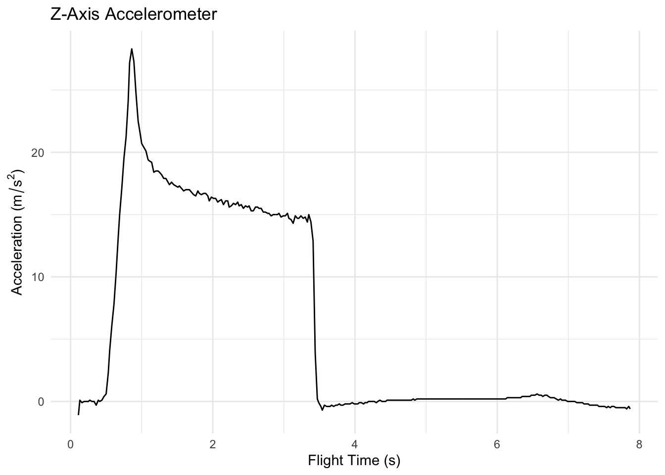
Here is the data from the accelerometer in the z-axis (up/down) direction.
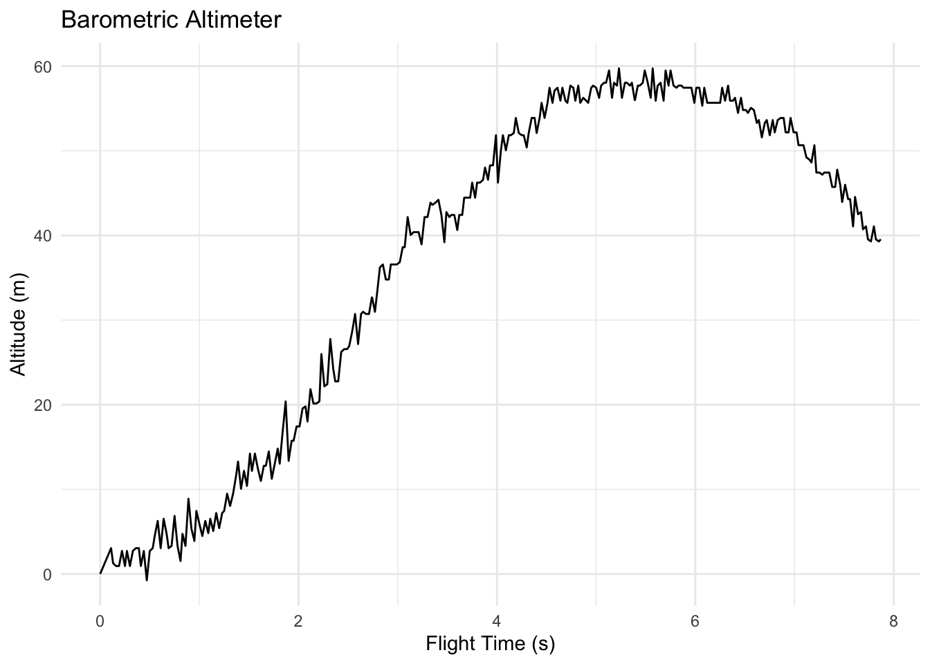
Here is the data from the barometric altimeter.
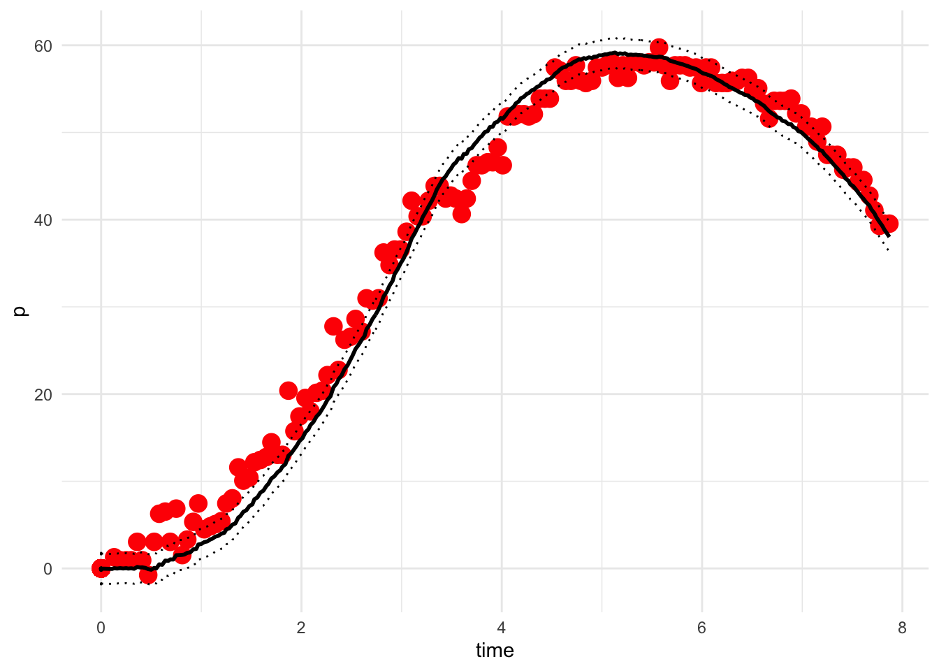
Here is an estimated track using downsampled altimeter readings (deleting every other value).
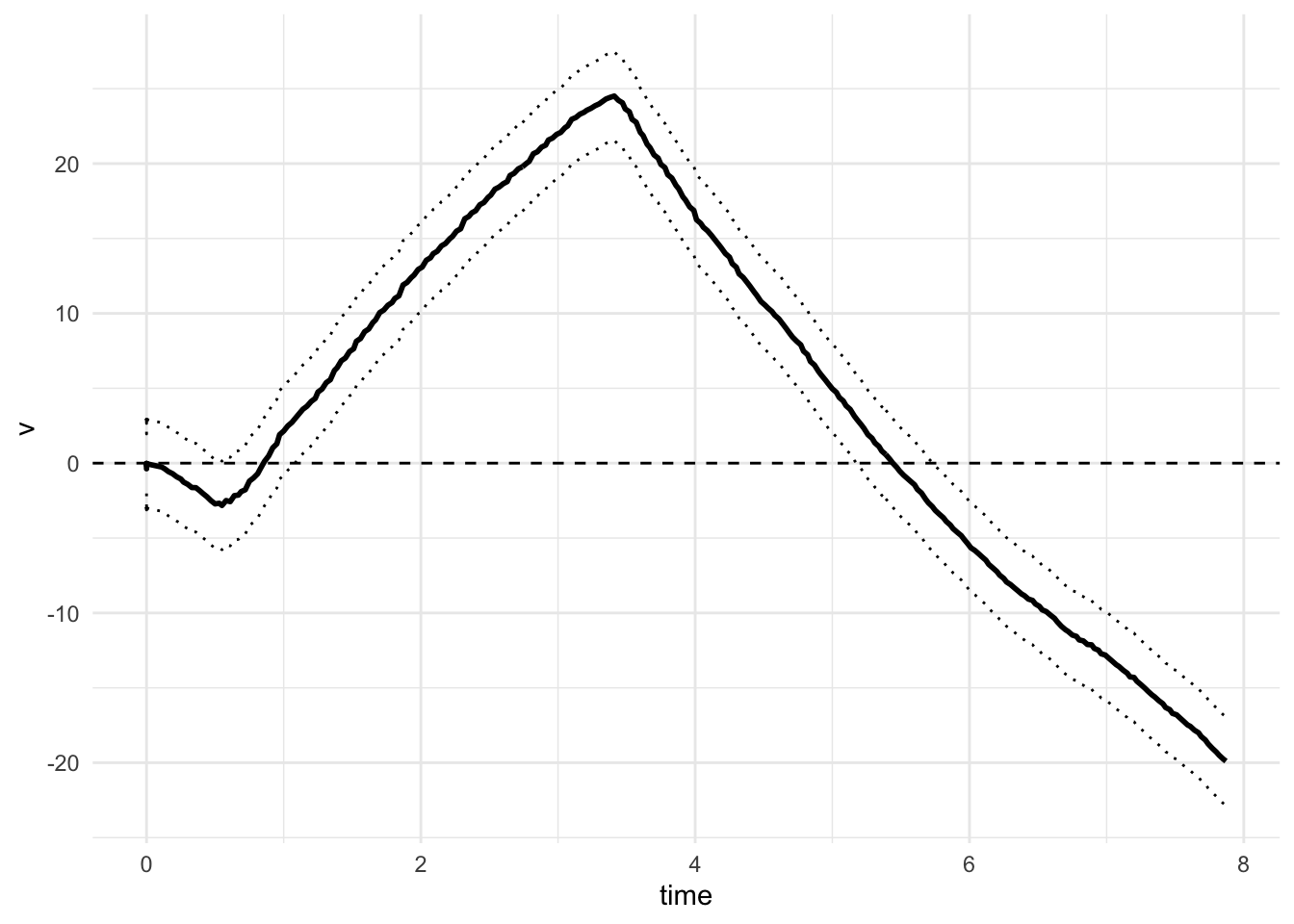
Here is the estimated velocity from the same model fit. The point where the velocity crosses zero is presumably where the apogee is located.