2 System overview
This section gives a brief overview of the P&H Mk2 skeg system as an introduction to the detailed notes.
The system consists of many components. In this section, we name each component in bold and try to use this name consistently throughout. Where possible, one word names are used. In commonly used terminology, the word ‘skeg’ is often used to describe some of these components (e.g. ‘skeg box’, ‘skeg cord’, ‘skeg blade’…). In the interests of clarity, we have chosen not to do this - it should be obvious that we are talking about something to do with the skeg, and one word names are preferred (e.g. ‘box’, ‘cord’, ‘blade’).
The skeg system consists of:
The actuator subsystem. Within the skeg box, the blade is pulled down by elastic and raised by the cord.
The connector subsystem. The cord runs within the tube from the skeg box to the ratchet box.
The controller subsystem. The slider box holds the cord at an adjustable position, setting the angle of the blade.
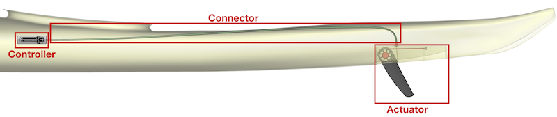
Each of these subsystems is described in overview below. The next 3 sections describe each subsystem and how to maintain it in greater detail.
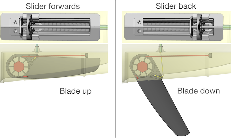
When the slider is set to the forward position, the cord is pulled through the tube and the blade is pulled fully up
When the slider is set to the back position, it releases some cord, allowing the blade to go down under the tension of the elastic.
2.1 Controller
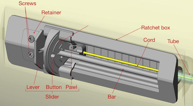
The ratchet box is bonded into the controller recess in the boat. A composite bar runs the length of the box, being retained at one end by a hole in the ratchet box and at the other end by the retainer. The retainer is held in place with screws. The slider runs along the bar. It consists of the button, the lever and the pawl. The cord is retained in the button with a knot.
The action of the slider box is easier to understand by looking at a section view:
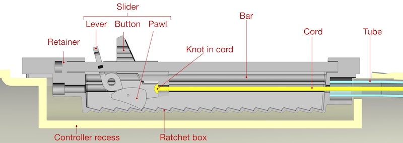
The bottom of the ratchet box has a ratchet surface, with a number of grooves. The pawl engages with one of these grooves under the action of a spring (not shown), preventing the slider moving under the tension in the cord (to the right in the image above). Because of the way that the ratchet surface is shaped, when the slider is pushed to the left, the pawl rides over the grooves, allowing movement. However, no movement is possible to the right unless the pawl is raised by squeezing the lever to the button.
The slider can thus be set at different positions, resisting the tension in the cord. This pays out different amounts of cord down the tube.
2.2 Connector
The connector subsystem consists of:
A polymer tube
A thin cord which runs through the tube
End fittings which connect the tube to holes in the boat at either end
Whilst the connector system seems simple, it can be fiddly to work with. In addition, there are several options for the end fittings at either end of the tube.
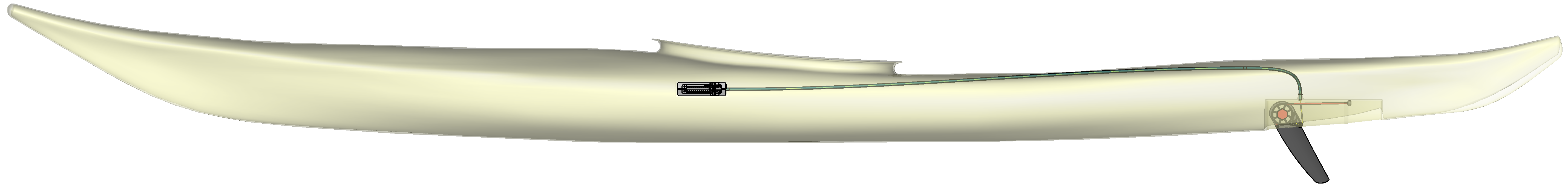
2.3 Actuator
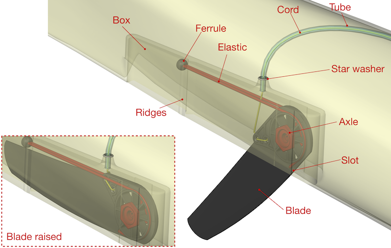
Near the stern of the boat, a recess called the (skeg) box is molded into the boat. The blade rotates on the 2 piece axle, which has male and female parts. The axle is located within a slot in the box. A length of elastic runs in grooves in the blade, tending to rotate the blade to the down position. The ends of the elastic are retained by a knot held in a ferrule which is prevented from moving forward by ridges in the box. The cord is tied to the blade and pulls it in the opposite direction to the elastic. One option for the tube end fitting, a star washer is shown in the diagram.