5 Actuator
The blade rotates on a 2 piece axle that jams into a slot in the boat’s skeg box. Elastic wraps around circular grooves in the blade and extends backward to a ferrule. The ferrule is restrained by ridges in the skeg box, preventing it from sliding forwards and thus applying tension to the elastic.
5.1 Removal and re-fitting of the blade assembly
Blade removal:
To remove the blade from the boat:
Move the slider to the rear, so that the blade deploys.
Pull the blade downwards out of the skeg box.
As the blade pulls out, allow it to pivot forwards.
Loosen the elastic from the grooves in the blade
Pull down on the elastics to remove the ferrule from the skeg box. It may help to free the ferrule with a long screwdriver.
Elastic and ferrule removed from boat. If you’re lucky you may be able to untie the cord at this point - although it is probably sensible to replace the cord if you’re replacing the blade. Once the blade is separated from the cord, or the cord is loosened from the slider, the blade assembly can be pulled free of the boat.
Blade refitting:
To re-fit the blade into the boat:
Hold the ferrule with one hand above and to the rear of the blade. With the other hand, run the elastics into the grooves in the blade
Ensure the elastics run all the way around the grooves before continuing
Push the ferrule into the skeg box behind the ridges that prevent it moving forward. Push the ferrule upwards as far as is easy with your fingers - there is no need to push it to full depth at this point
Align the axle with the slot in the boat’s skeg box.
Push the blade upwards, sliding the axle into position.
Swing the rear of the blade upwards to fully seat the ferrule.
Check that the blade can retract fully into the boat and that it rotates freely on the axle. If the blade does not seat far enough into the boat, take it out and screw the two halves of the axle together a little before trying again. If the blade does not rotate freely (or the axle is loose in the skeg box), try screwing the two halves of the axle apart a little. When making this adjustment, the elastics and ferrule do not need to be inserted into the skeg box.
It is easier to adjust the length of the cord at the controller end, although it is possible (if fiddly) to adjust the knot on the blade.
5.2 Replacing the elastic
The elastic can be adjusted as it wears by tying a knot closer to the blade, but ultimately a new length of elastic (shock cord) will be required. Remove the blade from the boat as described above. There is no need to untie the cord unless you are replacing it. Cut any cable ties securing the elastic to the blade and untie and remove the old elastic, keeping the ferrule.
It seems better to use 4 mm elastic for the replacement - this seems to work better than the 2 mm elastic fitted to some boats to reduce resistance with the old Mk1 controller. Cut the elastic to length (likely a bit shorter than the old stretched elastic) and pass through the hole in the blade that the old elastic passes through. Push both ends of the new elastic through the hole in the ferrule (this can take some fiddling and some force - pliers can help, as can putting a taper on the end of the elastic when you heat seal the ends). Tie an overhand knot in the ends of the cord to prevent it from slipping back through the ferrule.
Run the cords around the skeg blade grooves and hold the cord in tension as you replace the skeg blade and then the ferrule into position (see directions for re-fitting the blade above). Cable ties are not required to hold the elastic in place - P&H have used them on some boats but not others. It may be a little awkward to keep the cord in place during insertion into the boat, but it works fine if you maintain a little tension. Over time, the elastic sets a little into place and this becomes easier.
Adjust the tension (see below) and then replace the skeg blade into the boat (see above).
5.3 Adjusting the elastics
The elastics need to be taut enough to pull the skeg down, overcoming any friction in the system. They also need to keep the skeg deployed when the boat is moving at speed - this may be especially important for those using sailing rigs. However, if the line is too taut, it will be difficult to operate the slider to bring the blade back up and the elastic will likely age faster.
In order to adjust the system, deploy the blade and use a long screwdriver or a thin pair of pliers to remove the ferrule from the skeg box. Alter the position of the overhand knot on the cord - closer to the axle for more tension, further away for less. P&H have recommended applying just enough tension to hold the elastic straight with the blade fully deployed, then tying a knot 15 mm forwards of the ridges in the skeg box.
Replace the ferrule into its position and actuate the skeg blade manually to check the tension.
5.4 Adjusting the axle width
The red axle on which the skeg rotates is constructed from 2 parts which screw together. The parts are sometimes glued together, but a sharp twist should break the bond.
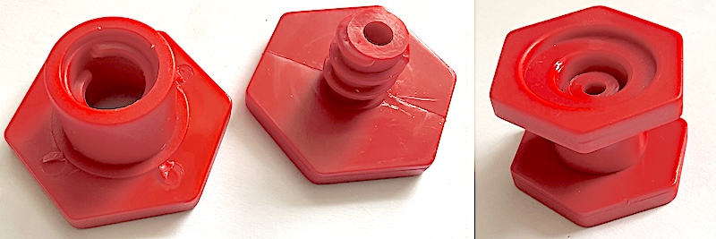
Twisting the hexagonal parts of the axle relative to each other allows the width of the axle to be adjusted. The slot in the skeg box prevents this rotation once the axle is installed. If the axle is set too wide, it will not fit into the slot. If it is set too narrow, the hexagonal parts will squeeze on the blade, preventing it from rotating freely.
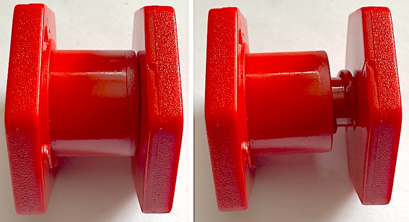
The slot is tapered. If the axle is made wider, it will sit a little lower in the slot. If it is made narrower, the axle, and thus the blade, will sit a little higher. This affects the length of cord that is needed in the system. When the skeg is retracted, there is a short length of cord between the top of the skeg box and the tie in holes on the blade. This length will be longer if the axle and blade sit lower. This must be borne in mind if adjusting the axle width. It also allows the user to use axle width adjustments to compensate for small errors in cord length, as a temporary fix.
5.4.1 Blade length
I once came across a problem with a Scorpio LV, where the blade needed a slight tug to bring it down through the first few degrees of operation. On close inspection, we found that the very tip of the blade was jamming into the back top of the skeg box. Seemingly, the blade was too long, or the skeg box was too short! My plan to gently file the end off was overruled by Pete from Summit to Sea who took an angle grinder to it, which solved the problem. Excellent (if slightly alarming) after sales support!
5.4.2 Blade spokes catching on axle part
If the mechanism feels like it is catching every few degrees, it may be that the spokes of the blade are interfering with the flats of the red axle component. The solution is to gently shave a bit of plastic off each spoke with a craft knife.
5.5 Skudder-type actuator
The skudder-type skeg is based on the Skudder system, in which the blade can be used as a rudder when fully deployed. In the skeg-only system, the blade is prevented from rotating. The controller and tube are the same as for the Mk2 system, but the actuator end is rather different.
Most of the system components, except for the blade assembly, can be seen by opening the actuator cover on the back deck of the boat. This is done by pulling the cover up, the reaching under it to release the cover elastic toggle to de-tension the elastics that hold it in place. The cover is re-fitted by pulling the cover elastic through the cover elastic toggle to tension it, then releasing the cover to drop back into its recess.
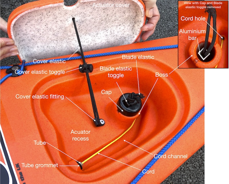
Below the Actuator cover is the Actuator recess, a hollow moulded into the boat. The Cover elastic fitting is screwed into the bottom of the actuator recess. The cover elastic runs from the cover elastic fitting to the actuator cover and holds the actuator cover in place. The Cover elastic toggle is used to tension the cover elastic.
The tube enters the actuator recess through the tube grommet. There is no fitting that positively locates this end of the tube. The cord exits the tube and runs around the cord channel (a channel moulded into the boat), and down the cord hold towards the blade.
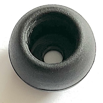
The blade fits to the aluminium bar which runs from the skeg box to the actuator recess, through a hole in the boss, a moulded feature in the actuator recess. The aluminium bar fits to the cap. The cap has a square feature which keys to the aluminium bar and ridges which locate in a slot across the boss - this prevents the aluminium bar from rotating. The blade elastic is attached to the blade assembly. The blade elastic runs through the centre of the aluminium bar and though a hole in the cap. The blade elastic is tensioned to hold the blade assembly into the boat by the blade elastic toggle and a knot.
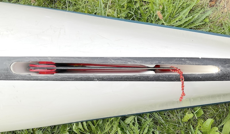
The blade assembly is shown below removed from the boat:
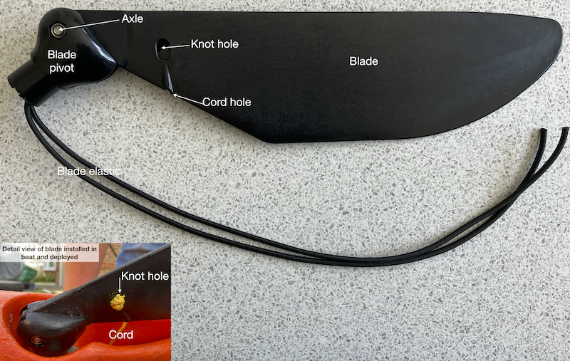
The blade assembly is supplied as a single part which is not intended to be disassembled. This single assembly contains the axle about which the blade pivots and a spring which pushes the blade down. As such, there is no need for a seperate axle and the elastics used in the Mk2 system to deploy the skeg.
The blade assembly consists of the blade and the blade pivots, connected by an axle about which the blade can pivot. A spring in the blade pivot rotates the blade out of the boat (anti-clockwise in image above, the blade is shown in the deployed position). The blade elastics are attached to the top of the blade pivot. The blade pivot has a recess that assembles to the aluminium bar.
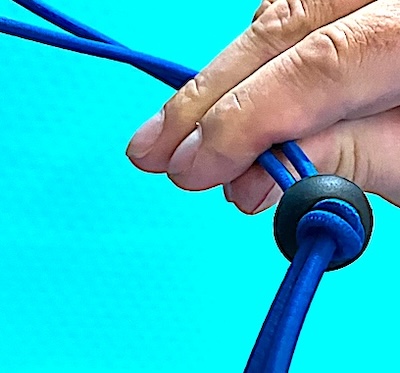
The cord passes through the cord hole in the back of the blade. It exists through the knot hole. A simple stopper knot in the cord here keeps it from pulling back out of the blade.
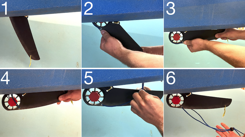
5.5.1 Blade assembly removal
To remove the blade assembly, begin by opening the actuator cover as described above.
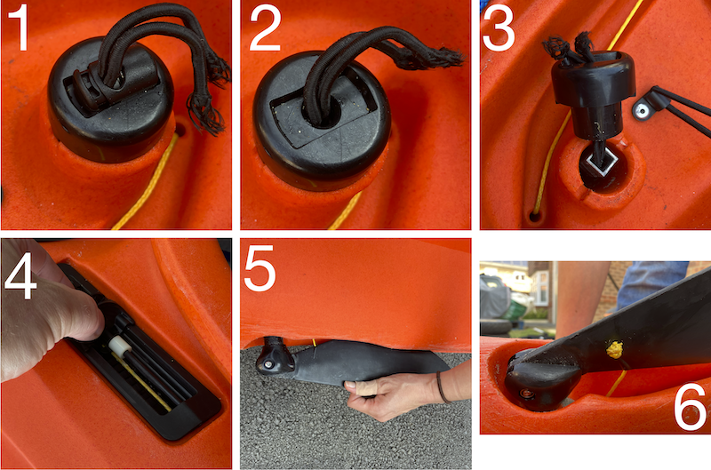
Then:
Untie the knot in the blade elastic
Remove the blade elastic toggle
Remove the cap
Move the slider to the back of the ratchet box such that the blade deploys
Pull the blade down and out of the boat, allowing it to rotate
Untie the knot in the cord and remove the cord from the blade
The blade assembly and also the aluminium bar can then be removed from the boat.
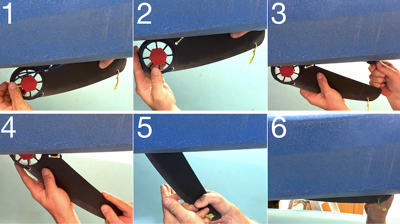
Reassembly follows essentially the reverse process:
Thread the blade elastics through the aluminium bar and fit the aluminium bar to the blade pivot such that it locks into the square recess
Place the blade assembly into the boat, running the aluminium bar into the large hole running to the actuator recess
Thread the blade elastic through the cap and then through the blade elastic toggle
Assemble the cap to the boss, ensuring the ridges align to the grooves in the boss
Tension the blade elastic with the blade elastic toggle and tie an overhand knot in the blade elastic
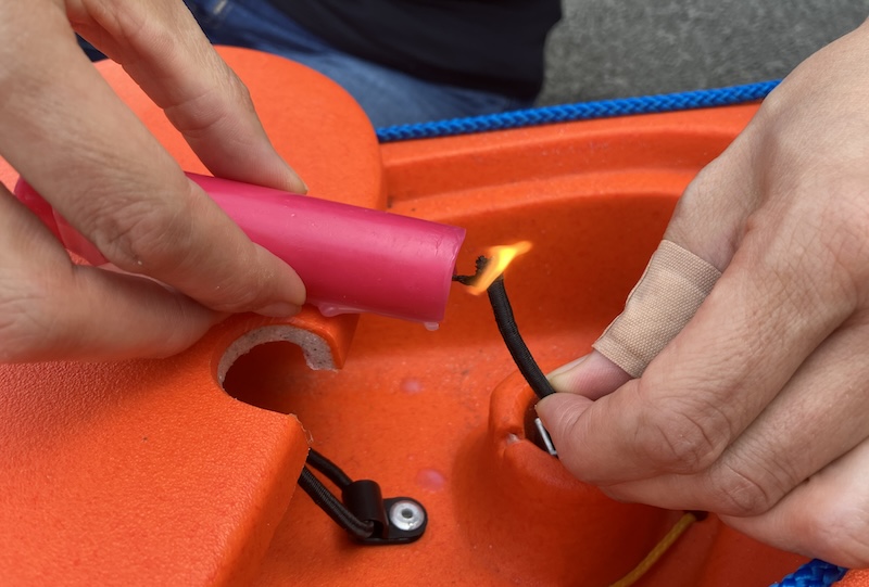
Many of the reassembly steps involve threading the blade elastic through various components. This can be fiddly, and pliers may help. Heat sealing the ends of the blade elastic helps. Use a candle to seal the ends of the blade elastic in situ.