3 Controller
The controller comes in Mk1 and Mk2 variants. The old Mk1 system ran on a stainless steel bar. It was eventually found that some of this bar drawn from the centre of the reel bowed more than that from the outside of the reel, causing interference and excessive friction in the mechanism. If possible, it is best to replace these with the Mk2. The Mk3 / Skudder system uses the Mk2 controller.
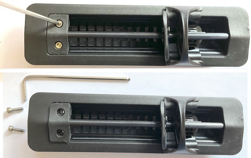
3.1 Controller dis-assembly
The controller may be disassembled using a 2.5 mm Allen key:
3.2 Inspecting components
3.2.1 Slider
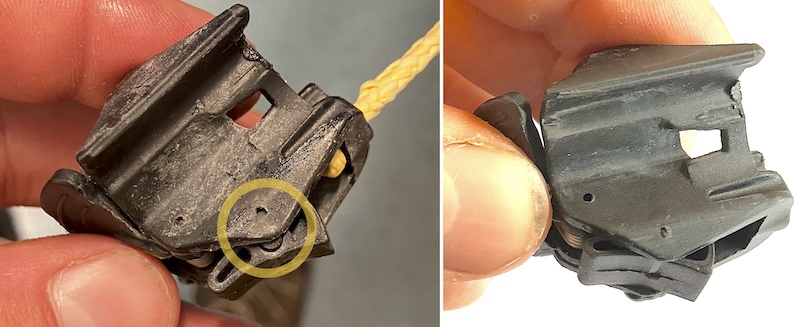
3.2.1.1 Broken pawl axle
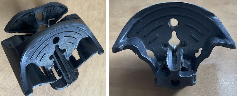
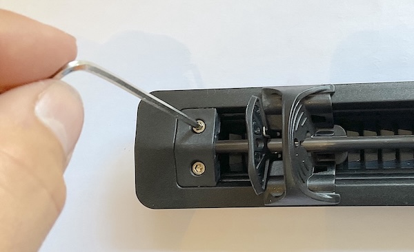
The button has pivots that appear to use thin plastic axles. These often break, making it hard to actuate the mechanism. If this happens, the pawl on the slider won’t sit straight - this is obvious when the slider is removed.
The image below shows a slider removed from the ratchet box with a broken axle on the pawl. The circular part on the pawl component (half of which can be seen poking out) should be concentric with the small notch in the button. This is clearly not the case with this broken component, which had just been removed due to the controller working poorly.
3.2.1.3 Wear on button rod runner
If the rod has become worn, wear may also occur where the rod contacts the button. If this occurs, the button likely needs replacing.
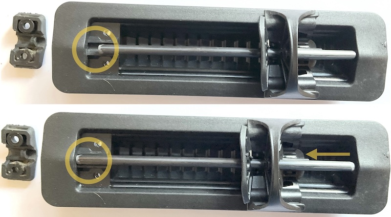
3.2.2 Rod
The composite rod tends to wear over time. The wear can be seen in the surface finish of the rod and the wear can be felt by rotating the rod between your fingers. It is sometimes possible to see or feel flats worn onto the rod.
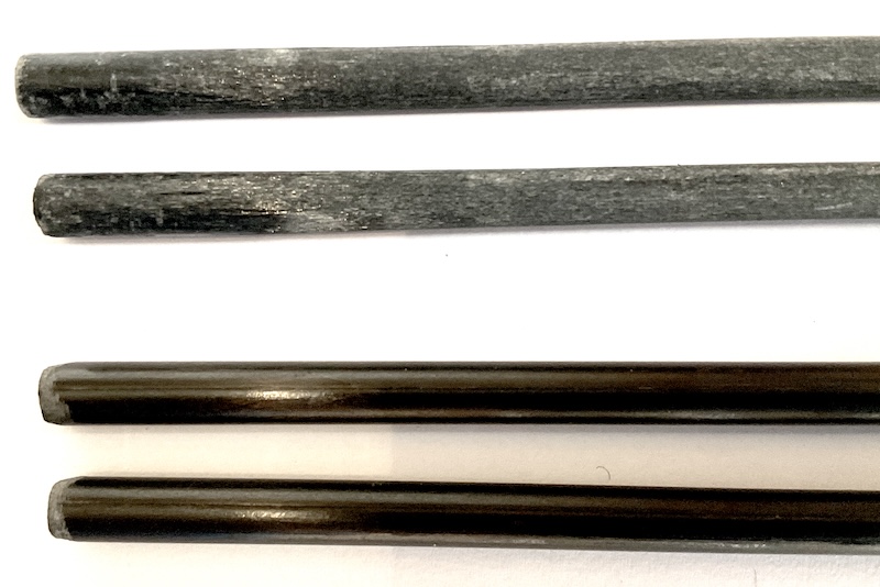
If the rod is worn, it can be replaced. An alternative is to rotate the rod when reassembling the slider box such that the slider is running on less worn surfaces.
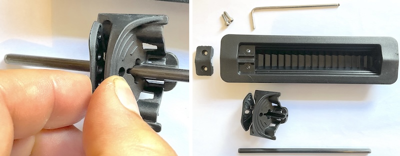
3.3 Controller assembly
Assembly is the reverse of the disassembly process. The lever is squeezed to the button and the rod slid into the slider.
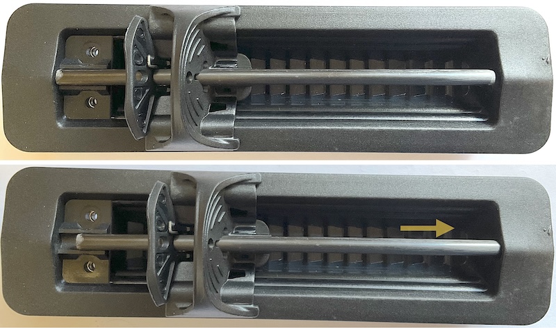
3.4 Setting cord length
The final adjustment to the system is setting the cord to the correct length and tying off in the button. The aim here is set the system so that:
- When the slider is pulled full forward the blade retracts fully into the boat
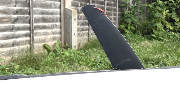
- When the slider is fully back, the blade should be at an angle of around 70˚ to the boat (such that half the lower cord hole in the blade can be seen )
The easiest way to set this is to work with the bar removed from the controller and to slide the slider forwards and backwards as if it were constrained by the bar. Make sure that you have taken any stretch out of the system - e.g. tie the cord off to the decklines in front of the cockpit and gently pull the skeg blade down. The process is easier with two people - one at the blade end to take the pressure off as needed, and one at the controller. Pass the cord through the hole in the bottom of the button, just by the pawl. Adjust the length of cord until correct, as described above. Mark the point where the cord meets the hole in the button with a black pen. The instructions say to tie 3 half hitch knots as a stopper at this point, which probably works with the old thin blue cord. With the new yellow cord, a single knot is all that fits into the space. Cinch the knot and check that the system operates correctly. Once you’re happy that the knot is at the right place, cut the cord near the knot, then reassemble the controller.
3.5 Ratchet box removal / replacement
The ratchet box component bonded into the boat will rarely need replacing. The most likely reason to want to do this is to replace a Mk1 ratchet box with the Mk2 version. The following instructions are for plastic boats. Due to the adhesives used on composite boats, replacement of the ratchet box is rather more difficult.
3.5.1 Removal of older ratchet box
Disassemble the controller and remove all the components.
The ratchet box is held in place with Soudaflex 40 FC polyurethane sealant. 3M 5200 adhesive can also be used. Applying heat to the ratchet box with a hot air gun weakens the adhesive sufficiently to enable the ratchet box to be removed by prying a screwdriver underneath it, but this will likely cause the ratchet box to be destroyed. Be careful to direct heat into the ratchet box and avoid heating the boat if possible and/or carefully apply force to avoid deforming the plastic around the ratchet box.
Scrape the old adhesive off the boat with a screwdriver
![]()
3.5.2 Prepare the boat for the new ratchet box
If you are replacing a ratchet box like-for-like, you can now move straight on to gluing the new ratchet box in place. However, if you’re upgrading to a Mk2 controller, you’ve got a bit of work to do first, as the hole for the cord needs to be in a slightly different place.
Although it’s not strictly necessary, the first thing to do is to weld the old hole closed. Whilst welding plastic is outside the scope of these notes, this is a fairly simple weld - get both the filler rod and the hole edge hot (they’ll go shiny when ready) then push the rod into the hole, twisting it to ensure good contact and to break off the end. I find it easier to place a few layers of tape across the back of the hole first in order to have a back surface to work against. Be very careful if the boat is a Corelite model, as it’s very easy to apply too much heat to the thin outer layer of plastic. Use the smallest flame setting on a small torch.
Find a drill bit of the same diameter as the cord hole in the ratchet box (don’t confuse this with the hole for the rod!). Put some ink (e.g. from a permanant marker) on the drill tip and use it to mark the boat through the cord hole.
Drill the hole. P&H recommend a 7mm drill bit to take the compression fitting for the 6 mm tube, but see notes elsewhere in these notes on skeg tube sizes and terminations. Now may well be a good time to replace the tube with the 8 mm tube used on newer boats. Hold the drill as parellel to the boat as you can.
3.5.3 Glue in the new ratchet box
In order to bond in a new ratchet box:
Sand both surfaces (boat and back of ratchet box)
Run a flame over the surface of both the boat and the back of the ratchet box
Apply 3 lines of adhesive to the boat’s controller recess (bottom of recess and either side) - Press in the ratchet box, use foam and masking tape to apply pressure whilst the adhesive hardens
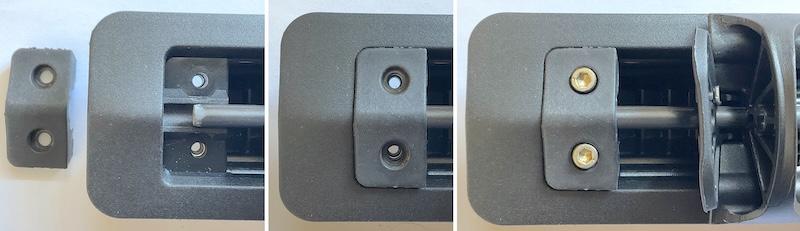
Ensure that the ratchet box is assembled into the boat the right way round - the screw holes should be towards the bow of the boat.
3.5.4 Reassemble the system
It should now be possible to reassemble the controller - see notes above.