Chapter 1 STRESS, STRAIN AND STRUCTURES
1.1 Stress and Strain
The deformation of a rock is the result of all the physical processes that act in its volume as a result of the applied forces. The forces acting on a rock volume originate stress and produce variation in the shape and volume of the rocks involved, called strain. In the deformation of rocks, the system can usually be considered not subject to accelerations, just as a closed system of forces in which the opposing forces are balancing. We can define a pair of forces as effort equal and opposite that act on a certain surface in a rock. These forces include the applied ones and the forces resulting from the reaction from the part opposite of the surface. The effort acting on a surface is indicated by the Greek letter \(\sigma\). The intensity of the effort depends on the intensity of the applied forces and the area on which these forces act:
\[\sigma = F/A\]
If we consider a surface with any orientation within a body, any force applied causes normal surface stress and shear stress parallel to the surface (Fig. 1.1A). The normal effort is indicated with \(\sigma_n\) while its shear stress is indicated with the letter \(\tau\). In three dimensions the shear stress \(\tau\) can be further decomposed into two further components, \(\tau_1\) and \(\tau_2\), orthogonal to each other.
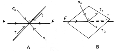
Figure 1.1: A) In two dimensions, normal stress \(\sigma_n\) orthogonal to a plane and shear stress τ, resulting from a force is applied on a plane; B) In three dimensions, the shear effort \(\tau\) can be decomposed into two shear stresses \(\tau_1\) and \(\tau_2\) orthogonal to each other; the force is applied on a surface in three dimensions can be then decomposed into three efforts, one normal and two parallel to the surface.
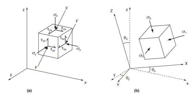
Figure 1.2: A) Stress components for a nitesimal cube subjected to a pair of compressive forces F in a coordinate system x, y, z. B) In a new reference system X, Y, Z it is possible to de ne a new cube in nitesimal with a new orientation on whose faces the shear stresses are zero, the stresses orthogonal to these faces are the principal stresses \(\sigma_1, \sigma_2\) and \(\sigma_3\).
To consider the three-dimensional state of stress on a point, let's imagine the effects of a system of forces on an infinitesimal cubic volume of rock (Fig. 1.2A).
The system of forces can be solved into a single force F acting on the center of the cube. Since the cube has infinitesimal dimensions, we can consider the forces acting on all faces of the cube equal to the force F. If we place the edges of the cube parallel to the axes of a reference system to each other orthogonal x, y, z, the components of the effort acting on the faces of the cube are nine: 3 on each face of the cube, opposite are the same. The nine components of the effort are:
\[\begin{matrix} \sigma_{x} & \tau_{\text{xy}} & \tau_{\text{xz}} \\ \sigma_{y} & \tau_{\text{yx}} & \tau_{\text{yz}} \\ \sigma_{z} & \tau_{\text{zx}} & \tau_{\text{zy}} \\ \end{matrix}\]
If the rock volume is not subjected to accelerations or rotations, the torques of shear stresses orthogonal to the axes x, y, z must be equal to each other but of opposite sign, to balance. Therefore we have:
\[\tau_{\text{xy}} = \ \tau_{\text{yx}}\qquad\tau_{\text{xz}} = \tau_{\text{zx}}\qquad\tau_{\text{yz}} = \tau_{\text{zy}}\]
and consequently, the nine independent components of the effort are reduced to six. So in any generic reference system with orthogonal axes x, y, z are required six effort components in order to fully describe the state of effort at a point. Instead of a generic reference system x, y, z (as in Fig. 1.2A), it is possible to choose a new reference system with axes X, Y, Z such that the components of the efforts of cut on the cube’s faces are zero (Fig. 1.2B), that is:
\[\tau_{\text{xy}} = \tau_{\text{xz}} = \tau_{\text{yz}} = 0\]
The three orthogonal planes on which the shear stresses are zero, are called principal planes of stress and the orthogonal stresses to them are called principal stresses. The main efforts are indicated with \(\sigma_1\), \(\sigma_2\), \(\sigma_3\) (with \(\sigma_1>\sigma_2>\sigma_3\). If the main efforts are known, the efforts acting on any plane variously oriented within a volume of rock can be calculated:
\[\sigma_{n} = \frac{\sigma_{1} + \sigma_{3}}{2} + \frac{\sigma_{1} - \sigma_{3}}{2}\cos{2\theta}\]
\[\tau = \frac{\sigma_{1} - \sigma_{3}}{2}\sin{2\theta}\]
What can be seen in two dimensions can be extended to the three-dimensional case, by considering a plane that identifies three angles \(\theta_1\), \(\theta_2\), \(\theta_3\) with the three main stresses \(\sigma_1\), \(\sigma_2\), \(\sigma_3\)
\[ \sigma =\sigma_1 cos^2 \theta_1 + \sigma_2 cos^2 \theta_2 + \sigma_3 cos^2 \theta_3 \] \[ \tau^2= (\sigma_1-\sigma_2)^2 cos^2 \theta_1 cos^2 \theta_2 + (\sigma_2-\sigma_3)^2 cos^2 \theta_2 cos^2 \theta_3 + (\sigma_3-\sigma_1)^2 cos^2 \theta_3 cos^2 \theta_1 \]
In any geological process in which rock is subjected to stress (deformation event) there is a variation of the position of the material points which make up the rock. This variation can be broken down into:
Translation and Rotation, i.e. displacement of material points in space without changing the shape of the body;
Deformation (strain), that is the variation of the shape of the body following the reciprocal displacement of material points.
In the case of translation (Fig. 1.3A), the movement of the body occurs without changes in shape and orientation. Moving with respect to the initial position, it is the same for any point of the body; In the case of rotation (Fig. 1.3B) the movement of the body occurs without variation of shape, but the orientation of lines with respect to a fixed reference system varies. The shift is greater for points that are further away from the pivot point; In the case of deformation, there is a variation in the shape of the body. The deformation that a body has undergone can be expressed by measuring the variation length of lines or the variation of angles between lines. The deformation related to the variation in length of lines is expressed by the extension, e (or longitudinal extension), that is the change in length per unit of initial length:
\[e = \frac{l_{1} - l_{0}}{l_{0}} = \frac{\mathrm{\Delta}l}{l_{0}}\]
where l0 is the initial length and l1 the length after deformation. The extension \(e\) will have positive values when l1>l0, when the deformation produces an elongation, negative for l1<l0, for shortening. The values of e are therefore included between \(-1\) and \(\infty\), as easily demonstrated by previous Eq. The extension is often expressed in terms of percentages (percentage extension, e%). To visualize the deformation undergone in a more intuitive way we consider a circle of unitary diameter in the undeformed rock (circle in black in Fig.1.3D). If the deformation is homogeneous, this circle will be transformed into an ellipse at the end of the deformation (black ellipse in Fig.1.3D-E), called the strain ellipse. In three dimensions will be deformed into an ellipsoid, the ellipsoid of the strain. The axes of the strain ellipse and the strain ellipsoid are called main axes of the strain and the extensions measured along these axes are the main strains.
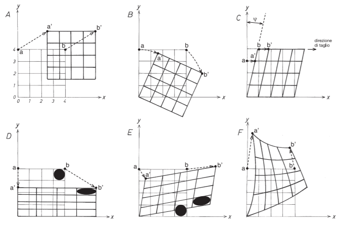
Figure 1.3: Possible types of displacements in space of the material points that make up a body. In all the examples the initial undeformed body is a square. A) Translation. B) Rotation. C) Simple cut. D) Pure cut. E) Generic homogeneous deformation. F) Heterogeneous deformation.
Every single deformation that the rock has undergone in every moment of its deformation history is called incremental strain. This process, from the undeformed rock to the rock in its final state by a continuous deformation over time through the overlapping of successive incremental strains, is called progressive deformation. Although deformation is the result of effort, there are no simple relationships between the orientation of the stress ellipsoid and deformation ellipsoid in a rock, in how much both can vary in orientation over time during the deformation history by simple shear (this type of deformation is thought to be one of the most used in nature, especially in shear areas, direct and reverse faults, along thrusts). As the shear strain increases, the strain ellipse becomes progressively more elongated and parallel to the cutting direction, corresponding in nature to the limits of a cutting area; in the initial states of a deformation by minimal strain increases (or in zones at low deformation), the shear strain has very low values. In the case of extension veins (tension gashes, Fig. 1.4) the orientation of the initial and final part of the vein, that is the area with less deformation, provides us with an indication of the orientation of the direction, elongation and shortening in the rock; in the case of shear zones, the shear strain is maximum in the central part of the shear zone cutting, while it decreases to zero as we approach to the limits of the cutting area; this explains why at the edges of the cutting zone the foliation forms an angle of 45 ° with i limits of the cutting area.
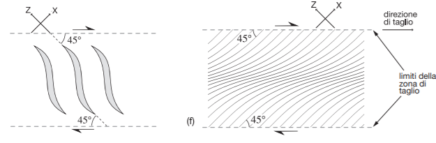
Figure 1.4: Sigmoidal tension veins (tension gashes) in a cutting area. (f) Orientation trend of the X axis of the strain in ellipse a cutting area (solid lines); at the center of the cutting area the cutting strain is greater than the limits of the cutting area; in the case of shear areas in metamorphic conditions that and in which recrystallization of minerals these lines correspond to the foliation trend.
1.2 Deformational Mechanism
How a stressed rock deforms is a function of numerous factors. It is a function of some external parameters such as pressure, temperature, applied stress, presence and nature of fuids, etc., and parameters of the rock such as mineralogical composition, size of granules, porosity, and permeability. The set of active material processes in a deforming rock defines a deformation mechanism and produces characteristic rock microstructures. Therefore, identifying the mechanism operating during deformation is based on the recognition of microstructures that this produces. The deformation mechanisms that can operate in rocks are:
Cataclasis, in which there is fracturing, loss of cohesion and sliding between the granules;
Plasticity, with intracrystalline deformation due to movement of dislocations or by twinning;
Viscous sliding, in which the strain is accommodated by the diffusion of matter;
Dissolution and Reprecipitation (pressure solution), with solution and transport of matter assisted by the presence of intergranular fluids.
The deformation mechanisms of plasticity, creep and dissolution and reprecipitation lead to a viscous flow activated mainly by temperature, while the deformation mechanism of cataclase leads to a flow with relative sliding of the grains (frictional flow) strongly dependent on pressure and it’s the process in which this thesis work is framed.
1.3 Cataclase
Cataclase is a deformation mechanism in which the grain size decreases due to the development of microfractures on all the stairs, on which there is sliding. This leads to an increase in volume (dilatancy, Fig. 1.5), to a relative sliding between the grains along fractures and passive rotation between grains or grain fragments.
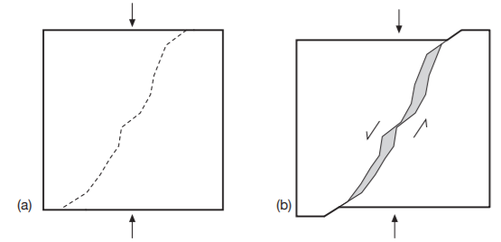
Figure 1.5: A) Development of a fracture in a crystal and B) sliding of the two parts. If the fracture is not on a flat surface there will be the formation of voids (in gray) which lead to an increase in the total volume of the rock (dilatance).
Generally, there is a decrease in the grain and the degree of sorting of the rock during this process, with a wide spectrum of granule sizes. Slipping along fractures or between granules is strongly influenced by normal stress applied (frictional); equally a function of the applied stress is the dilatancy, i.e. the possibility of increasing in volume. It follows that resistance, that is the possibility of a rock to deform by cataclase, is a function of the effective pressure at which the rock is subjected and, therefore, of depth. Temperature, strain rate and rock composition are of subordinate importance in this deformation mechanism. The temperature becomes important only if as a result of extremely fast deformations; it can increase a lot, up to producing a partial melting of the forming rock, named pseudotachylites. The term pseudotachylite refers to a glassy rock formed as a result of very rapid movements along a fault plane, often inside fragments of the surrounding rock, spherulite-like structures and minerals only can be recognized partially melted or corroded. The contact between the pseudotachylite and the host rock is sharp (Fig.1.6).
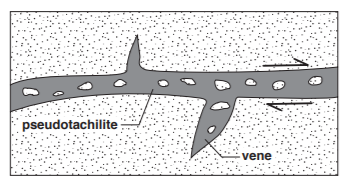
Figure 1.6: Pseudotachylite pattern (grey) in a fault plane
The deformation mechanism of cataclase can be active
in a localized deformation, for example, along faults or in shear areas.
In this case, the thickness of the cataclasite is much smaller than the
size of the fault or shear zone. Cataclase can also operate in
non-localized deformations, with a strain distributed in a wide band. In
this case, we are talking about deformation due to cataclastic flow. The
development of brittle deformation in a rock, that is, associated with
the formation of fractures, is strongly influenced by the pressure
conditions present, since there is the formation of fractures, veins, etc.
This type of deformation is accompanied by an increase in the total
volume of the rock (dilatancy). For this reason, brittle deformation is
very common at superficial structural levels, while decreasing in
importance with depth. A stressed body will break, producing a fracture
that moves when a shear force is applied on its surface. Only a few basic
physical mechanisms exist for fragmenting a rock, and on a first-order
approximation, it is possible to distinguish physical from chemical
brecciation. Chemical brecciation, or corrosive wear, is caused by
selective dissolution, whereas the main mechanism for physical
brecciation occurs when the amount of stress exceeds the brittle
resistance of the material. However, numerous processes occur during
fracture propagation in a hydrothermal system, such as subcritical crack
growth, which allows cracks to propagate below the strength limit of the
rock by combining mechanical and chemical processes. Brittle fracturing
may appear in response to various stress fields of different
origins with very different scales and relative timing.
The sources for the stress can be divided into two categories (Bott and Kusnir, 1984):
renewable, which persists despite continuing stress relaxation and
corresponds to tectonic activity, and nonrenewable, which can be
dissipated by relief of the initial strain, e.g., bending and
thermal stresses. The corresponding processes will be called
incremental and instantaneous, respectively. Eight main mechanisms of
brecciation can be defined (Fig. 1.7). Tectonic comminution,
fluid-assisted brecciation and wear abrasion are the most common and are
widely represented in vein-type deposits. Volume reduction, volume
expansion, impact, collapse and corrosive wear are usually less
abundant. It is important that these mechanisms are not treated as
discrete processes, but rather as parts of a continuum in geological
environments.
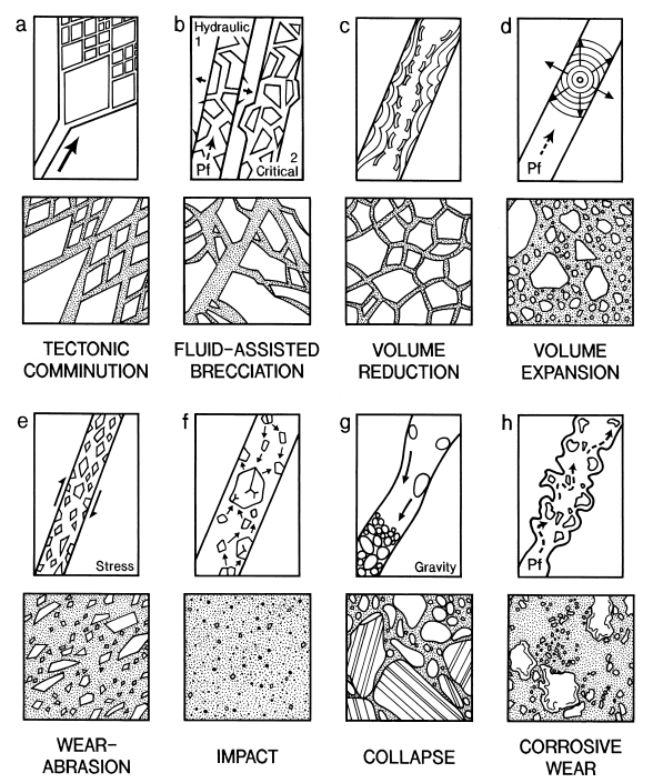
Figure 1.7: Schematic illustration of the brecciation mechanisms and resulting geometry of the breccias. Large arrow (tectonic comminution). indicates the direction of fault propagation. Small arrows indicate direction of displacement of the wall (fluid-assisted brecciation, volume expansion). or fragments (impact, collapse). Pf is fluid pressure. No scale is indicated, as most of the geometry is fractal.
1.3.1 Fracture propagation
Hydrothermal breccias develop early during vein formation in response to the fracture propagation. This process is well documented in structural geology studies (Scholz, 1990) and is one of the most common mechanisms of brecciation. Fracture propagation can be observed at all scales, from millimeter-sized fractures to kilometer-long faults which ‘enclose’ fragments of the hanging wall and footwall rocks. Numerous interactions occur between microfragments during small-scale fragmentation and these interactions are collectively referred to as wear abrasion. Fracture propagation and wear abrasion together are the two components of tectonic comminution. Brecciation associated with fracture propagation generally develops in association with persisting stress, and failure occurs when some critical stress is attained. However, in cases of long term loading, natural fractures can also grow at stress intensities below critical stress (subcritical propagation; Atkinson, 1984). Tensile and compressive failure may occur, but tensional processes will generally dominate because rocks are much weaker under tensional rather than compressional forces. Breccias caused by brittle tectonic comminution typically display fragments with angular morphology, especially in tensile fractures. Fault development comprises two steps: firstly, an initiation of an array of en-echelon cracks and secondly, linkage of the cracks to form larger faults (Segall and Pollard, 1983; Granier, 1985). En-echelon cracks commonly display a general periodicity, caused by a random distribution of defects, a low-speed fracture propagation, and near-equilibrium in the system. As the system evolves, the propagation of the fracture may occur more rapidly because of the increasing fragility of the media. Arborescent branching can occur during the propagation of the shear zone reflecting the instability of the propagation mechanism and the speed of propagation itself, related to stress intensity.
1.3.2 Fluid-assisted brecciation
Fluid is abundant at every level of the crust, especially in its more brittle part (Fyfe et al., 1978). In hydrothermal systems, the most frequent brecciation process is hydrofracturing, related to temporal variations in the fluid pressure (Phillips, 1972; Je´brak, 1992; Hagemann et al., 1992). The process
of fracture formation and disjunction of the fragments can be divided into two steps: hydraulic fracturing and critical fracturing: (Fig.1.7).
Hydraulic fracturing is related to an increase in the fluid pressure within the vein. This causes a decrease in the effective pressure, which can lead to fracture propagation. Most hydraulic fracturing is produced in an extensional regime, although it can also occur in a contractional environment. The increase in fluid pressure may have several origins, including a decrease in fault permeability due to fault slip or mineral deposition, and effervescence or boiling as a result of chemical reactions. Most of these processes are transient and brecciation will commonly mark one or several specific moments during mineral deposition. Brecciation can appear before or during vein formation, but because it will tend to preferentially occur in rocks with low permeability, it will frequently be observed at the beginning of the infilling process prior to extensive fragmentation.
Critical fracturingis related to the destruction of the equilibrium between the fluid pressure and the regional stress within a vein. Fluid pressure decreases in response to a sudden space opening generated by rapid slip or the intersection between different veins. Therefore, any increase in the porosity of the system, especially after hydraulic fracturing, will provoke decompression and spalling instabilities on the vein wall. The best-documented examples are implosion breccias in dilational jogs. This explains why crosscutting veins are commonly associated with zones of intense brecciation. This type of brecciation typically develops during vein formation and has been frequently observed in mesothermal gold deposits.
Hydraulic and critical brecciation are always strongly associated because they are both associated with variations in fluid pressure. Both of these types of fluid-assisted brecciation generate in situ fragmentation textures (mosaic breccias). In a puzzle pattern without significant rotation of the fragments, rotation can often be observed in critical brecciation because the fragments generally collapse immediately following the fragmentation. This latter process may even appear in rather deep environments, such as mesothermal lode gold deposits where tilted host rock blocks demonstrate the initiation of collapse processes. An absence of rotation indicates that critical brecciation did not occur extensively and that the dilation process in the vein was a transient phenomenon with a limited amount of open space. In fluid-assisted brecciation, fragments are angular and brecciation typically follows pre-existing planes of discontinuity, like bedding or schistosity. This is related to the relatively low amount of energy required for hydrofracturing. Pressure fluctuation may also cause hypogene exfoliation which could locally lead to rounded fragments. However, this type of process is usually a combination of both chemical and physical processes.
1.3.3 Wear abrasion
Wear abrasion, or friction, occurs whenever a solid object is loaded against particles of a material that have equal or greater hardness (Fig. 1.7E). In vein-type deposits, it occurs following the propagation process. Quartz typically acts as a wearing agent because of its hardness. Several micro-mechanisms occur concurrently during wear abrasion, including small scale fractures, cutting and fatigue by repeated plucking. Grain plucking is strongly dependent on the grain size of the brecciated rock and can be very important for coarse-grained rocks (Stachowiak and Batchelor, 1993). Wear abrasion may evolve into cataclastic flow- a deformation mechanism that involves uniformly distributed microcracking combined with rotation and frictional sliding of the fragments. The physics of these processes is very complex and far from fully understood, especially because of the different behavior of the system at different scales. At the macroscopic scale, fabrics formed during abrasion can be confused with those of a ductile process, yet these fabrics are obviously produced by the rearrangement of an aggregate of rigid grains at the microscopic scale. However, it is possible that the transition between brittle and ductile behavior may arise due to the microplasticity of material in high pressure and high fluid-rock ratio context. Such a process is common to all brittle geological environments, but since frictional strength increases with effective pressure (effective normal load; Byerlee, 1978), the process is more commonly developed at depth. Repetitive sliding could cause fatigue-related cracks to form, producing large wear fragments. Fragments in wear-abrasion breccias will commonly display rounding by rotation in the rock. Dissolution–recrystallization occurs under pressure and will add textural complexity to the boundaries of the fragments. Wear abrasion is one of the few processes that produce a large variety of particle size distribution types, from normal to fractal.
1.3.4 Volume reduction
Fragmentation by volume reduction is not a common process in natural systems, but can occur due to phase transitions or temperature variations. The most common volume reduction process is desiccation, which seldom occurs in hydrothermal systems. Desiccation is a form of brittle fracturing characterized by a polygonal network of extensive joints and is a transient process (Fig. 1.7). During a layer of homogeneous material contraction, desiccation creates a tessellation pattern and produces cracks perpendicular to the cooling or shrinking surface. It will produce identical brecciation to that formed by desquamation processes in the surficial environment. Fragments of approximately the same size characterize the particle size distribution of desiccation breccias. Crack networks are not fractal because contraction-crack polygons generally have a characteristic length related to the elastic properties and thickness of the contracting medium.
1.3.5 Volume expansion
Volume expansion is generally related to transient explosion phenomena (Fig. 1.7). This mechanism is related to an unusual stress field, called a Hertzian stress field, where \(\sigma_1\) (maximum principal stress) decreases progressively from the center of propagation of the fracture. This type of stress field can be generated by an explosion or impact between an indenter and a surface (Frank and Lawn, 1967). The crack growth is orthogonal to the most tensile principal stress \(\sigma_3\) . and corresponds to a surface delineated by the trajectories of \(\sigma_1\) and \(\sigma_2\). Cracks may deviate from the stress path. Explosions can be provoked by chemical reaction, rapid decompression. or phreatic explosion, although true explosion-related breccias are rarely found in hydrothermal veins.
1.3.6 Impact brecciation and collapse
When the walls of a vein are far enough apart, particles removed from the wall by brecciation may travel downward or upward in the fluid and be abraded. In this manner, a vein may act as an autogenous mill when dilation is large enough to allow some mobility of the fragments. The dominant physical process involves particle-particle and particle-host rock impacts in such an environment. Cupelling and chipping will occur. Impact brecciation, also known as erosive wear, relates to the ballistic behavior of such fragments in the fluid, where multiple reflections of collisional shock waves cause brittle fracturing to develop within a Hertzian stress field specific to each particle. Each particle can record a complex and dynamic evolution, and all the kinetic energy of the impacting particle is converted into elastic energy. In a vein-type system, the more important factors will be particle strength, size and impact velocity. Impact brecciation is highly effective for ductile materials because even a high speed fluid without particles can be erosive, as demonstrated by the damage done to aeroplanes while flying through clouds. Impact brecciation and wear abrasion can both occur during the same brecciation event. The geological distinction between these two processes can be made based on fragment mobility and fragment brittle–ductile deformation. Impact brecciation has seldom been recognized as a major mechanism for breccia formation in hydrothermal veins, although it may be much more prevalent than previously realized. Hydrothermal media are usually very dynamic, especially near the surface, and hydrothermal minerals commonly contain solid microinclusions that may be interpreted as xenoliths formed as the result of erosive wear. In volcanic environments, the ‘mill rock’ commonly associated with massive sulfide deposits is composed of rock flour probably formed by impact brecciation. However, these rocks remain fairly uncommon and impact breccias are typically restricted to transient events during which exceptional acceleration of the flow allows particles to migrate rapidly and usually upward. Impact breccias may also be generated within hydrothermal veins during collapse processes which cause fragments to be transported downward (Fig. 1.7). Collapse breccias are usually the result of increased spalling of the vein walls. Fragments of the host rocks and early minerals may fall into the conduit and subsequently interact together
1.3.7 Corrosive wear (chemical brecciation)
Chemical brecciation is very common in natural environments. The product is known as a solution breccia or a pseudobreccia (Je´brak, 1992); the process is called corrosive wear. In the lithosphere, salient examples are produced by magmatic brecciation, hydrothermal processes and the rounding of granitic rocks during weathering. Sahimi and Tsotsis, 1988 proposed a general model for corrosive wear by studying the consumption and fragmentation of porous coal particles. Two reaction-consumption end members were defined as the kinetic and diffusion-limited regimes. In the diffusion-limited regime, only the most exposed part of the solid matrix is reached and consumed as a reactant; corners are therefore much more easily dissolved than a flat surface, and so the external surface of the fragments will become smooth and fragments may ultimately take a spherical morphology.
Such a process will occur if there is a strong chemical disequilibrium between the rock and the fluid. The alteration–dissolution rate is limited only by the chemical reaction rate in the kinetic regime. A uniform alteration will conserve the overall morphology of the fragments and indicate the presence of a fluid with relatively low chemical reactivity. In hydrothermal veins, chemical processes are plentiful. Corrosive wear may occur at different times during the infilling events. Any crushing process that significantly increases the reactive surface can enhance corrosive wear. Corrosive wear will give several types of fragment morphology. Diffusion-limited regime processes produce smooth fragments, whereas kinetic regime processes enhance the contrasting compositions of the fragments and result in more complex final morphologies.
1.4 Breccia evolution
During vein formation, the host rock undergoes profound transformations as it changes from a cohesive to a fractured medium and then to a percolating medium. Propagation, two-media and threemedia stages can be distinguished, each of which represents specific brecciation processes (Fig. 1.8).
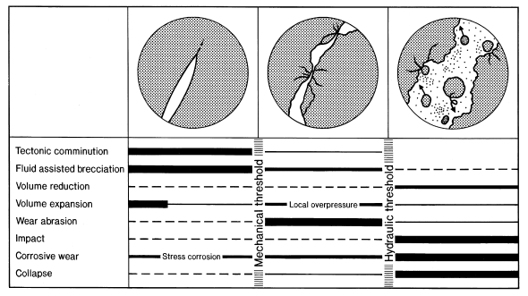
Figure 1.8: Three stages of breccia formation within hydrothermal veins: propagation, wear, and dilation stages, separated by two thresholds related to mechanical discontinuity and hydraulic continuity
Two major thresholds separate these stages: a mechanical discontinuity threshold when it becomes a noncontinuous solid, and a hydraulic continuity threshold when the fluid forms a continuously connected phase throughout the fracture system. The three stages can repeat in a cyclic manner in hydrothermal systems, allowing for very complex brecciation patterns to arise. The mechanical discontinuity threshold marks the transition from a solid medium to an assemblage of fragments. At this stage, there is no longer a continuous cohesion throughout the wall rock, and stress and strain within become much more heterogeneous than before. The hydraulic continuity threshold marks the transition from an assemblage of discrete pockets of hydrothermal fluid separated by zones of interconnected wall rocks, to a permeable aquifer. During this stage, fluid pressure will be highly variable, and may even evolve from lithostatic to hydrostatic if the fault is connected to the surface. Thermal and chemical reequilibrations between individual fluid pockets may occur and hydrothermal solutions can be transported along the entire length of the fault.
1.4.1 Propagation stage
The propagation stage involves the nucleation and growth of fault patterns. The main mechanisms involved are tectonic comminution, fluid-assisted brecciation
and, less commonly, volume expansion by hydrothermal explosion (Fig. 1.8). Fracture propagation can be enhanced by stress corrosion, a mechanism that involves alteration at the tip of a fracture, thereby inducing corrosive wear. Fracture initiation is an highly nonlinear process, and the entire process is strongly dependent on the pre-existing anisotropy or heterogeneity of the rock.
Fracture propagation creates the abundant and widespread breccias associated with faults. In natural systems, brecciation is either caused by a rapid release of energy or a more long-term renewable process (Bott and Kusnir, 1984). If the energy input is generated by nonrenewable stress for a short period of time, brecciation could be a one-step process, as in the case for explosions and implosions. Volume reduction processes belong to the same one-step process because cooling and desiccation are almost instantaneous in a geological time frame. If the energy input is protracted in response to renewable stress, incremental fragmentation will occur whereby a series of other fracture events follow the initial fracture event. On the other hand, brittle comminution may be associated with either quasi-uniform or nonuniform directed stress. Fig. 1.9 is a two-dimensional illustration of the four hypothetical different stress configurations that lead to different fracture patterns, either instantaneous or incremental. During quasi-uniform stress, \(\sigma_1\), \(\sigma_2\) and \(\sigma_3\) remain constant. This may be accomplished in a purely tensile system associated with regional stress, or in an extensional fracture network caused by volume reduction. Most of the strain during brittle comminution will be accommodated by numerous simple tension cracks typically accompanied by minor branching (Bahat, 1980). Local stress variations at the microscopic scale may form in response to fracture propagation, but such variations are generally minor. In such systems, strain in a perfectly homogeneous media can become localized with some periodicity due to the redistribution of the stress under subequilibrium conditions. Such periodicity is not only predicted by mathematical modeling, but is also observed during experiments (Wu and Pollard, 1995).
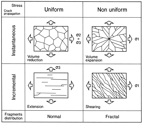
Figure 1.9: The two parameters of stress and crack propagation play a major role during the propagation stage, and define early fragmentation. Crack propagation can be instantaneous, related to transient, nonrenewable, stage of stress, or incremental constant state of stress. The stress field could be relatively uniform, like in a tensional environment, where few rotations occur, or nonuniform, like in a compressional environment. Arrows indicate one of the principal stress directions.
1.4.2 Wear stage
The wear stage represents the longest period of breccia formation in a hydrothermal vein-type deposit. After the initial propagation stage, the mechanical threshold is crossed and the medium becomes discontinuous. Displacements along the fault wall usually occur several times before reaching complete hydraulic continuity of the medium. Such tectonic movements are related to the seismic cycle (Sibson,1986) and earthquake rupturing, and are associated with limited fluid circulation and sealing by mineral deposition. Energy will be partitioned for both fracturing and the differential motion of the blocks, thus modifying the packing geometry and the porosity. Several mechanisms of brecciation will be operating, among which wear abrasion will be dominant (Fig. 1.8) although the large fluid pressure variations could also provoke fluid-assisted breccias. Reactions between the fluid and the host rock can cause local corrosive wear breccias to form, whereas sudden changes in the physical state of the fluid can create volume expansion/explosion breccias.
Wear abrasion will occur because of the roughness of the vein walls and the evolving geometry of the conduit during this stage of breccia evolution. Also during this stage, an abrasion process resulting from the relative movement between the two sides of a fault will mostly control breccia formation. The abrasion process may be controlled either by the roughness of the surface of the walls or by the mineralogical characteristics of the gouge. The rapid changes in the geometry of the rock during the wear stage will promote fluid pressure fluctuations which can modify the effective stress and the physical state of the fluids. Fluid-assisted brecciation (hydrofracturing) will be one of the common processes during wear stage and indicates the high pressures easily sustained by a medium with relatively low permeability. Fragments may also collide with each other causing intraparticle fracturing and autogenous brecciation.
1.4.3 Dilation stage
The third stage of breccia evolution is characterized by dilation and appears after the second critical threshold when the fault network becomes connected
and fluid percolation can occur. At this point, the medium becomes hydrodynamically continuous. Its permeability increases suddenly, with possible transitions from lithostatic to hydrostatic confining pressure. Several types of breccias may be formed during this stage, including those related to corrosive wear and open space physical processes e.g., collapse and impact. Corrosive wear is dependent on the time-integrated water–rock ratio. This ratio will rapidly increase after the establishment of hydraulic continuity, allowing hydrothermal fluids to percolate around each fragment. Impact brecciation and wall erosion may occur and will be facilitated by the availability of hydrothermal fluids that can chemically weaken the material. However, at the same time, the appearance of a vertical hydraulic gradient in the conduit allows the fluid to be transported with a higher flow rate and the residence time will be shorter. Others mechanisms of brecciation will be of lesser importance.
Volume reduction is limited to very specific colloidal deposition and does not appear to play any major role. The transition from a lithostatic to a hydrostatic
regime induces instability along the wall rock and abundant collapse breccias may mark the later phases of hydrothermal vein-type deposits. The dilation stage could become pulsative if there is strong cementation during the process (i.e., mineral precipitation) resulting in a cohesive breccia. Spalling from the vein walls is related to decompression events. The combination of accretion of hydrothermal minerals around fragments and collapse within newly formed cavities could lead to the formation of cockade breccias (Genna et al., 1996), with reverse graded bedding of the fragments.
1.5 Structures in Deforming Rocks
The term "brittle" referring to a deformation has a precise mechanical meaning and implies the deformation mechanism of cataclasis, that is, a type of deformation in which it has the formation of fractures and in which the strain is accommodated by sliding of grains along them. An equally clear definition from a mechanical point of view does not exist for the Term "ductile". By “ductility” we mean the ability of a material to deform. A rock with a ductile behavior, if subjected to stress, can acquire a certain amount of strain before breaking. However, a certain deformation can be ductile at a certain observation scale and not be more on another scale. It can therefore be said that all the rocks having undergone deformation show a ductile or brittle deformation depending on the observation scale. To describe the characteristics and deformation mechanisms in a deformed area (e.g. fault, cutting area, etc.) it is therefore more appropriate to distinguish between "localized deformation/non-localized deformation" or between “transition from brittle behavior (cataclasis) to plasticity".
| Minerale | Temperatura |
|---|---|
| Anidrite | 70°C |
| Calcite | 180°C |
| Quarzo | 270°C |
| Feldspati | 450-500°C |
| Olivina | 700°C |
Cataclasites are formed in the presence of a localized deformation, as a result of a localization of the strain leading to the development of a fault zone. Cataclasites are rocks in which most of the strain is accommodated by the deformation mechanism of cataclase. Cataclastic rocks are generally characterized by fractures and alterations. It is possible to distinguish non-cohesive cataclasites (friction breccias) from cohesive cataclasites. The cohesion can be original (possessed also during deformation), or be acquired secondarily following cementation phenomena. In nature Cataclasites much smaller thicknesses (from a few centimeters to a few kilometers) than their longitudinal extension (from a few meters to several tens of kilometers). It is therefore justified to think that work softening processes take place during deformation (or strain softening) which lead to the localization of the deformation. The principal ones include:
Variation of the deformation mechanism: The mechanisms of dynamic recrystallization (e.g. recrystallization by rotation) can lead to a decrease in size of granules and therefore to a change in the deformation mechanism, towards in a mechanism such as viscous sliding. All of this can occur if the dimensions of recrystallized granules are suffiently small (<10 \(\mu m\)) and if there are other mineralogical phases that prevent subsequent growth. This variation is often documented in carbonate Mylonites.
Geometric localization: In shear areas the recrystallization processes lead to the development of preferential crystallographic orientations and to the orientation of reticular planes on which there is movement of dislocations parallel to the limits of the cutting zone. This, leads to work softening and localization of deformation, is common in Quartz-Mylonites and Olivine-Mylonites. Localization of deformation can occur in rocks with a plus phase easily deformable that reorganizes itself to form continuous levels, or in rocks where a pre-existing anisotropy rotates to orient itself parallel to the cutting area.
Presence of fluids: The presence of interstitial fluids can lead to a reduction in resistance by one rock and its fracturing and deformation at lower than normal stress values. Common in Serpentinite, Gypsum or Igneous rocks that deform in the sub-solidus state, that is still in the presence of melt.
Reaction softening: During the deformation, fluids can induce syntectonic reactions whose products are small-grained minerals that trigger viscous deformation mechanisms. In other cases there may be reactions that transform more competent minerals into more easily deformable minerals (eg Quartz, Chlorite, Sericite, etc.).
Chemical softening: The drastic reduction of the strength of a rock can occur as a result of sinmetamorfic reactions, which leading to the local concentration of trace elements or water contained in the crystal lattice (hydrolitic weakening).
Shear heating: In a deformation under medium stress conditions (<100 MPa) the heat that develops can be dissipated by conduction from rocks surrounding the cutting area.
Figure 1.10: Localization of Deformation following dynamic ricristallization
1.6 Textures in Deforming Rocks
By texture we mean the preferential crystallographic orientation of the constituent minerals or clasts of a rock; the term microstructure, on the other hand, refers to all the characters of a rock observable on a microscopic scale, such as the presence of a foliation or traces of them, shape and orientation of granules, evidence of deformation (deformation bands, sub-grains, recrystallized grains), morphology of grain contours, etc. In a deformed rock we can have two extreme cases with:
A lot of texture weak or absent and a microstructure with a strong grain shape orientation (Fig. 1.11a);
A strong texture and a poorly oriented microstructure (Fig. 1.11b).
Dynamic recrystallization mechanisms often lead to an oriented microstructure and simultaneously with a very strong texture (Fig. 1.11c).
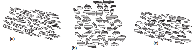
Figure 1.11: (a) Aggregate with preferential shape orientation (oriented microstructure) and no preferential crystallographic orientation (texture). (b) Aggregate without preferential orientation of form but with a preferential crystallographic orient ation. (c) Aggregate with oriented microstructure and texture oriented.
1.7 Kinematics Indicators
During a deformation event in a rock other foliations can develop in addition to the main one (complex foliations); the angular relationships between the various foliations represent kinematic indicators. The most common types of complex foliation used to determine the sense of movement are the S-C surfaces and the shear bands.
1.7.1 S-C Surfaces
Oblique foliage can form between them because in nature in a non-cut area there is an homogeneous distribution of the strain, but could formed levels in which the deformation is greater than isolating areas in which the deformation is less (strain partitioning). The higher deformation levels develop a penetrative foliation than for high values of strain is subparallel to the limits of the cutting zone (surface C, from the French Cisaillement) (Fig. 1.12). In the less deformed portions, on the other hand, the minerals will be only partially rotated in the direction of transport and will form a larger angle with the boundaries of the cutting zone. These latter minerals define another foliation (surface S, from the French Schistosité) oblique to the surfaces C.

Figure 1.12: Orientation of S-C surfaces
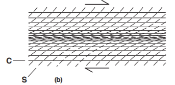
Figure 1.13: Orientation of S-C surfaces
Observation of the angular relationships between the surfaces S and C provide us information on cut direction. In a profile through a cutting area (Fig. 1.13) the angle between these surfaces decreases towards the center of cutting zone, where the deformation is usually greater.
1.7.2 Shear Bends
This term refers to small-scale cutting zones in Mylonites, with synthetic movement respect to the general sense of transport. Locally the Shear bands cut the Mylonite foliation, but after a short stretch they become parallel to it and subsequently they gradually lose importance. The angle the Shear bands form with the Mylonite foliation gives indications on the direction of cutting. During the process of milonitization, therefore, there is a displacement of material along the anisotropic surface (the foliation) and not parallel to the limits of the cutting area, which is incompatible with the general geometry in, as there would be an increase in thickness. Consequently, the presence of local cutting areas is necessary (shear band) with normal fault-like geometry immersing in the transport direction (Fig. 1.14b).
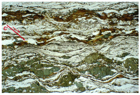
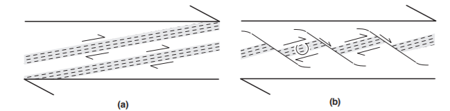
Figure 1.14: Formation of shear Bend in some cutting zone
Shear bands are known in literature with various names: Shear band foliation, C 'plans, Extensional crenulation cleavage, etc. Actually we talk about Extensional Crenulation cleavage only for any crenulation cleavage on which it is possible to recognize extensional movements. The difference between shear band and extensional crenulation cleavage is highlighted by that the shear bands are syn-Mylonite, very discontinuous and after a short distance they parallelize with the Mylonite foliation. In the case of extensional crenulation cleavage the surface have instead a greater discontinuity and cut any previous foliation indifferently; their development is therefore not contemporaneous with that of the main foliation and should not be used as kinematic indicators.
1.8 Fabric in fault rocks
The geometric organization of rock’s components and their spatial configuration defines the Fabric of a rock, which includes the texture, structure and orientation of the different components (minerals or clasts). Two types of fabric can be recognized: the primary fabric that develops during rock formation, and the tectonic fabric that is formed as a consequence of the deformation. This provides clues for the reconstruction of the deformation state, the kinematics of deformation, the transformation times, and the bending geometry, all elements that contribute to recognising and reconstructing a region’s tectonic evolution.
Depending on geometry of the elements that originate it, the fabric can generally be distinguished into planar fabric (or foliation in which the weaving element is planar, i.e. it is shorter in one dimension than the other two), and linear fabric ( or lineation in which the element of weaving is linear, i.e. it is longer in one dimension than the other two). As for the fault rocks, we can mainly distinguish 3 different fabrics that indicate the evolution stage of breccias and/or the spatial location of the rock with respect to the actual shear zone (proximal or distal).
The embryonic fabric is typical of coarse breccia zones near the boundary with the damage zone and consists of an assemblage of large fractured angular grains, which are in contact with one another (Fig. 1.15a). A fine matrix is in a very incipient stage of development. The grain size distribution is generally well-sorted toward the largest sizes.
The intermediate fabric is also typical of the breccia zones (i.e. the portion lying near the gouge zone). It consists of an assemblage of several large grains, which are partly in contact with one another and partly surrounded by a fine matrix (Fig. 1.15b). The large grains are less angular than those observed in the embryonic fabric. The grain size distribution of samples with an intermediate fabric is less sorted than that observed in samples with an embryonic fabric (e.g., Storti et al., 2003; Billi et al., 2003a; Billi, 2007).
The mature fabric is typical of gouge zones and consists of an assemblage of a few large grains surrounded by a well developed and abundant fine matrix (Fig. 1.15c). Large grains are rarely in contact with one another and are generally well rounded (e.g., Heilbronner and Keulen, 2006; Storti et al., 2007). Grain sorting within samples with a mature fabric is usually poor; the grain size distribution is shifted toward the small grains as compared with that typical of the breccia zones (i.e., embryonic and intermediate fabrics) (e.g., Billi, 2007).
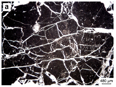
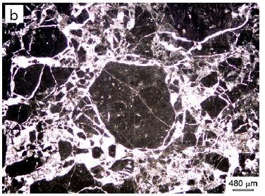
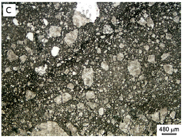
Figure 1.15: In (a) coarse and angular grains are in contact with one another (embryonic cataclastic fabric). Small grains forming a fine matrix are almost absent. Note the network of extensional fractures. In (b) coarse grains start to be rounded and surrounded by a fine matrix (intermediate cataclastic fabric). In (c) coarse grains are rare and rarely in contact with one another because an abundant fine matrix surrounds them (mature cataclastic fabric).
1.9 Application of microstructural analysis
Fragment geometry can be used as a tool for recognizing their diverse origins. Two geometric parameters appear to be especially useful for this purpose:
Fragment geometry, either simple or complex, can help distinguish between chemical brecciation of the kinetic type and the various kinds of mechanical brecciation. However, it is not possible to identify an origin based only on a rounded fragment shape, since that shape may be related to several different brecciation processes, including fluid-assisted, impact or chemical.
Fragment distribution (PSD) allows several different processes to be distinguished. A PSD value close to 1 is indicative of fragmentation related to volume diminution. A low PSD value is often observed in hydraulic breccia or in breccias where transportation processes provoke a size classification. In such cases, the distinction between process should be made using other methods, such as the nature of the fragments. Higher PSD values indicate large differences in fragments size that correspond to tectonic fragmentation (tectonic comminution or wear abrasion) and can be distinguished using the amount of displacement between the fragments. Very high PSD values are typical of fragmentation by explosion processes (Grady and Kipp, 1987).
These two geometric parameters can be used to construct a classification diagram for hydrothermal breccias. For example, roughness (Dr) and PSD (Ds) can define fields for the different breccia-forming environments which account for the main breccia types (Fig. 1.16). Boundaries in the diagram are approximate
because there is not enough data from natural examples and because of the considerable overlap between breccia types. This type of diagram could also be constructed for other geometric parameters which express the complexity of the geometry of individual fragments in relation to the type of particle size distribution.
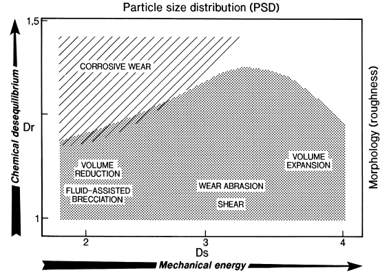
Figure 1.16: Diagram of Dr (roughness fractal dimension) vs. Ds (particle size distribution) showing the approximate fields of the different types of breccias