Chapter 3 Work and heat in closed systems
Thermodynamics is the study of energy and energy conversion. Often we are interested in the conversion of heat into shaft work. The burning of coal or nuclear fission generates heat. This heat is converted into shaft work which can readily be converted into electricity in a generator. We will study the different ways of converting heat into work and the limits to this conversion later. In this chapter we will only look at how work is performed in a closed system. Then we will also introduce heat transfer.
3.1 Closed and open systems
An important step in any analysis is to define the system we want to study. The system is a properly defined region in space. The boundaries of this space is called the system boundary. The system boundary has zero thickness. This means anything is either inside or outside of the system. The system boundary separates the system from the environment or the surroundings. Energy in the form of heat can cross the system boundary and the system can perform work or work can be done on the system. We distinguish between open and closed systems.
In the case of open systems, mass can flow across the system boundary, in and out of the system. The system boundary usually encloses a device. Examples of open systems are hair dryers, boilers or turbines. A closed system is often also called a control volume.
A closed system consists of a fixed amount of mass enclosed by the system boundary. No mass flows across the system boundary. It is often also called a control mass. A piston-cylinder arrangement is the most common closed system. We encounter piston-cylinder arrangements in internal-combustion engines, the engine of steam locomotives and reciprocating air compressors. As the temperature or pressure of the system changes, the volume of the system will change and with it, the shape of the system boundary. The piston-cylinder arrangement in an internal combustion engine is only a closed system during the compression stroke and during the power stroke. During the other strokes one of the valves is open to either allow the air/fuel mixture to flow into the cylinder or the combustion products to flow out of the cylinder.
We begin our discussion on work and heat transfer with closed systems. As a closed system transforms from one state to another, it passes through an infinite number of intermediate states. We assume that the deviation from equilibrium19 of these states are infinitesimally small.20 This is called a quasi-equilibrium process. This means that the pressure and temperature gradients in the system are negligibly small. In other words, at any moment during the process, the pressure has a single specific value, temperature has a single specific value and specific volume has a single specific value that is valid at any position inside the system boundary – in other words, the temperature, pressure and specific volume are uniform. These assumptions are valid for processes taking place very slowly. How slow the process must be in order for us to assume quasi-equilibrium, is not important now. Assuming uniform pressures and temperatures inside the system boundaries for processes taking place at finite rates gives us valuable insights into real processes.21 We will encounter several types of processes e.g. an isothermal process, where the temperature of the system stays constant or an isochoric process where the volume stays constant.
3.2 Work
If a force with a constant magnitude of \(F\) is necessary to move a weight a distance \(s\), the work is given by the product: \(W=F \times s\). Consider a gas inside a piston cylinder setup as in Figure 3.1.
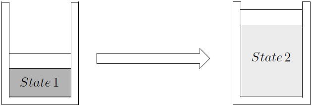
Figure 3.1: Expansion of gas.
The gas inside exerts a force on the piston. In general the force is not constant during the process. Therefore, the magnitude of the work performed by the system in the process of going from state 1 to state 2, is given by:
\[\begin{equation} W = \int_1^2 F \, \text{d} x \tag{3.1} \end{equation}\]
where F is the force exerted on the piston and is equal to the pressure of the gas multiplied by the area of the piston and \(x\) is the vertical position of the piston. It is usually easier to work with the identical formulation:22
\[\begin{equation} W_{out} = \int_1^2 P \text{d} V \tag{3.2} \end{equation}\]
where \(P\) is the absolute or total pressure inside the piston and \(V\) the volume of the the system. This is a closed system and the system boundary encloses the gas insides the setup. This work is called boundary work because it is performed at the boundary of the system. If pressure is measured in \(kPa\) and volume in \(m^3\), work is in \(kJ\). Work done by the system on the environment (volume increases) will be a positive number while work done by the environment on the system (volume decreases) will be a negative number because the value of \(P\) is always \(>0\). To perform the integration and determine the magnitude of \(W\), a relationship is required between the gas pressure at the moving boundary and the volume of the system. In real processes this relationship may be difficult or even impossible to obtain because of pressure gradients in the system or an unknown relationship between pressure and volume. However, if we assume a quasi-equilibrium process we can define different process paths between the two states.23
For a few special processes, the relationship between pressure and volume can be expressed as a simple mathematical equation.
3.2.1 The Isobaric Process
If heat is added slowly (Sonntag and Borgnakke 2012 Par 1.4) to a gas (or liquid or vapour/liquid mixture) in a frictionless piston-cylinder arrangement such as in Figure 3.1, the gas will expand, push the piston upwards and the volume will increase without the pressure inside changing. This is so because the pressure inside is the result of the combined effect of the ambient pressure and the mass of the piston - none of which is dependent on the volume of the gas. The assumption is that the expansion takes pace slowly enough that the force necessary to accelerate thee piston is negligible. The pressure will also remain constant when heat is removed and the volume of the gas inside decreases slowly.

Figure 3.2: Constant pressure process.
As pressure is constant, \(P\) can be taken out of the integral sign in Equation (3.2) and the equation for work becomes:
\[W_{out} = P(V_2-V_1)\]
where \(P\) is the (total) pressure of the gas inside the piston/cylinder set-up. With \(P\) in \(kPa\), and \(V\) in \(m^3\), the units of \(W\) is \(kJ\). It is clear that the work performed is equal to the area under the graph as shown in Figure 3.2. This fact can be also used to calculate work or when an analytical integration is not possible - as will be discussed later.
3.2.2 The Isothermal Process
Consider a piston cylinder set-up with a number of weights on the piston. When one of the weights is removed, the gas will expand and the temperature and pressure will drop. Heat can be added to keep the temperature constant. Perform this expansion process gradually and slowly (Sonntag and Borgnakke 2012 Par 1.4) and add heat at a sufficient rate to keep the temperature constant. Then, for an Ideal Gas the process path on a P-V graph will be a hyperbole as shown in Figure 3.3 because \(P=mRT/V\) and m, R and T are constant. For an Ideal Gas the area under the curve can be determined analytically by eliminating \(P\) in Equation (3.2) by using the Ideal Gas Law (\(P=mRT/V\)) and integrating to get an expression for \(W_{out}\):
\[W_{out} = mRT \, \ell n \left({\frac{V_2}{V_1}}\right)\]
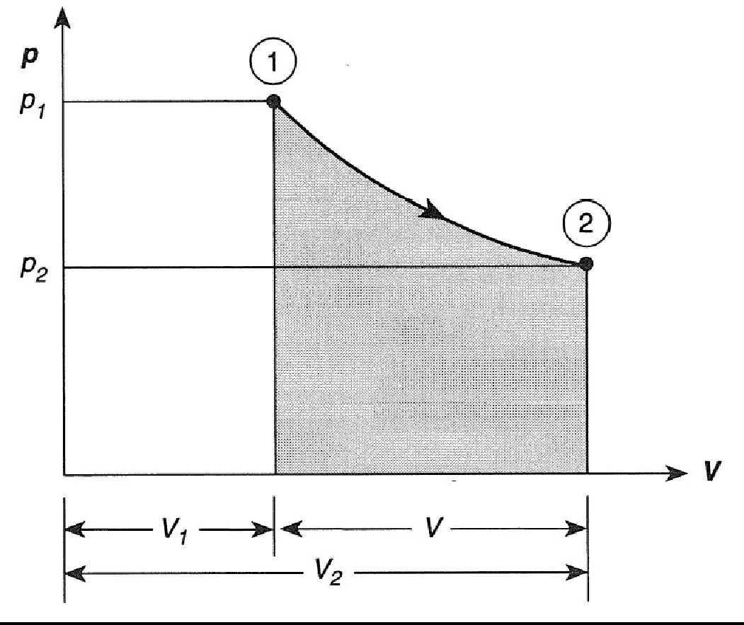
Figure 3.3: Isothermal expansion of a gas.
Example
One kilogram of air at \(25^\circ C\) and \(100kPa\) in a piston cylinder arrangement is compressed slowly to a pressure of \(200kPa\).
Heat is released at a sufficient rate to keep the temperature constant during the process.
Calculate the work.
Solution
The initial and final volumes can be calculated using the Ideal Gas Law: \(V_1=0.8557 m^3\) and \(V_2=0.4278 m^3\)
\[\begin{aligned} W_{out} &= mRT \, \ell n \frac{V_2}{V_1} \\ &= 1\times 0.287 \times 298.15 \, \ell n \frac{0.4278}{0.8557} \\ &=-59.3kJ \end{aligned}\]
The value is negative because work was performed on the air in reducing its volume and raising its pressure. The convention in this text is that the numerical value of work is always a positive number therefore the answer is reported as:
\[W_{in}= 59.3 kJ\]
If the Ideal Gas Law is not valid, an analytical integration is not possible but it may be possible to determine the area under the curve numerically as shown in Figure 3.4.
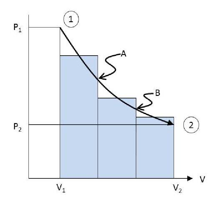
Figure 3.4: Isothermal expansion of steam.
Select a number of convenient intermediate pressures (or volumes) and determine the corresponding values of volume (or pressures) at the given temperature. Point 1 on the graph is then the volume of the steam at the specified temperature and \(P_1\). Point A, the volume at the specified temperature and \(P_A\) etc. If enough intermediate points are chosen, it can be assumed that line segment 1-A is a straight line. The area under line segment 1-A is then the same as that of a rectangle with a height \(\frac{(P_1+P_A)}{2}\)) and width of \((V_A-V_1)\). The areas of the other two rectangles are calculated in a similar fashion. The sum total of the three areas of the three rectangles give an approximation of the area under the curve.
3.2.3 The Adiabatic Process
In an adiabatic process, the system is well insulated so that no heat transfer takes place between the system and the environment. If ideal gas can be assumed and if the specific heats (Paragraph 4.1.2 for the gas can be assumed constant (usually the case for the mono-atomic gases He, Ar, Ne and Kr), the relation between pressure and volume during a quasi-equilibrium process, is given by the following equation:24
\[\begin{equation} PV^k = c \tag{3.3} \end{equation}\]
The exponent \(k\) is equal to the ratio of the specific heats \(C_p\) and \(C_v\). Its value can be found in a table of ideal gas properties.25 The numerical value of the constant (c) for each process will be different and must be determined from the conditions at some stage of the process — for instance the initial conditions \(P_1\) and \(V_1\). Using Equation (3.3) to get an expression for pressure in terms of volume, \(P=cV^{-k}\), Equation (3.2) can be integrated:
\[\begin{equation} \begin{aligned} W_{out} &= c\int_{V_1}^{V_2} \! V^{-k} \, \mathrm{d} V \\ &= \frac{c}{1-k}\left(V_2^{1-k}-V_1^{1-k}\right) \\ \end{aligned} \tag{3.4} \end{equation}\]
If a gas is compressed, the kinetic energy of the particles is increased by the approaching boundary - much like a cricket ball being hit by a bat for a six - and the temperature of the gas rises. The temperature of a gas that is expanded adiabatically, drops. The reason is that the particles colliding with the expanding boundary, must perform work to move the boundary and will therefore lose some of their kinetic energy and therefore the temperature drops. A common mistake is to assume the temperature in an adiabatic process remains constant. Although there is no heat transfer, there is energy transfer in the form of work.
Example
One cubic meter Helium at \(25^\circ C\) and \(200kPa\) in a piston cylinder arrangement is expanded adiabatically to twice its volume.
Calculate the work, final pressure and final temperature.
Solution
Because this is Helium and assuming a quasi-equilibrium process we can calculate the work using Equation (3.4) but we need to know the value of \(c\).
Using the initial conditions, Equation (3.3) can be used to calculate the value of \(c\) as equal to \(200\).
Therefore:
\[\begin{aligned} W_{out} &=\frac{200}{1-1.667}(2^{-0.667}-1) &=111kJ\\ \end{aligned}\]
The pressure at the end of the process (\(P_2=62.98kPa\)) can be calculated using Equation (3.3) and the temperature at the end of the process (\(187.8K\)) using the Ideal Gas Law.
Equation (3.3) gives the relationship between Pressure and Volume for a perfect gas undergoing an adiabatic process. In Paragraph 4.3 where Equation (3.3) is derived, it is also shown that using the Ideal Gas Law and after some manipulation of Equation (3.3) the following more convenient relationship including temperature, is valid for Perfect gases undergoing an adiabatic process:
\[\frac{T_2}{T_1}=\left( \frac{P_2}{P_1} \right)^{\frac{k-1}{k}}=\left( \frac{V_2}{V_1} \right)^{1-k}=\left( \frac{v_2}{v_1} \right)^{1-k}\]
It is left to the reader to confirm that this equation will give the same values for the final pressure and temperature.
3.2.4 Process with Spring Restrained Piston
If the piston is restrained by a linear spring, the \(P\)-\(V\) relationship of the process will be a straight line. The area under a straight line is easily determined. The work can be determined by drawing the process on a graph and calculating the area under the P-V line.
3.2.5 The Isochoric Process
In an isochoric process the volume stays constant and no work is performed. The area under a the curve of an isochoric process drawn on a \(P\)-\(V\) diagram is zero.
3.2.6 Polytropic processes
For and isothermal process \(PV^1=constant\), and for a perfect gas undergoing an adiabatic process, \(PV^k=constant\). Some textbooks define a polytropic process for which the power for \(V\) lies somewhere between 1 and \(k\). This makes it possible to calculate work analytically for such a process. The numerical value of the power may be determined from fitting a curve to experimental values.
3.2.7 Non-equilibrium processes
In all the previous cases we assumed quasi-equilibrium processes - therefore uniform conditions prevailed inside the system (a single value of P and T could be used to represent the pressure and temperature of the component). Although this is often a good assumption, there are cases where it is clearly not a valid assumption. In order to calculate the work done in such cases, integrate Equation (3.1) using your engineering judgement.
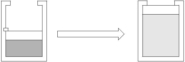
Example
Air at \(25^\circ C\) and \(600kPa\) is contained in a piston cylinder arrangement with a cross sectional area of \(0.1m^2\).
The initial volume of the air is \(1m^3\). The mass of the piston is \(100kg\).
The atmospheric pressure is \(87kPa\). The piston is kept in position by a pin as shown in the sketch.
The pin is removed and the piston moves rapidly upward until it hits the stops. The final volume is \(3m^3\).
Calculate the work.
Solution
The combined effect of the weight of the piston and the atmospheric pressure means the piston will be able exert a pressure of \(96.81kPa\) on the air once it is free to move.
This is the pressure necessary to lift the piston at constant velocity and push away the atmosphere.
In actuale fact, the pressure exerted by the air on the piston is initially \(600kPa\) and is more than \(96.81 kPa\) throughout the process.
This will cause a net upward force which will accelerate the piston upwards.
However, the piston comes to a standstill against the stops and the kinetic energy of the piston will be converted into heat and sound.
The net effect is however that he piston was moved upwards and the atmosphere pushed away – in effect a constant pressure process with a pressure of \(96.81kPa\). The net work performed by the air is therefore:
\[W_{out}=96.81(3-1)=193.62kJ\]
It is clear that the air performed more work in order to accelerate the piston but that the additional work was lost as heat and sound. Using the Ideal Gas Law and assuming a frictionless piston and uniform pressure inside, it should be possible calculate the acceleration, velocity and displacement of the piston as function of volume and piston elevation and then calculate the actual work. However, this is beyond the scope of this text.
Also, the pressure inside will most probably not be uniform and at a certain value of volume there will not be a single value for pressure that can be used in calculations and then it will therefore not be possible to present the process on a P-V diagram and determine the area under the curve - analytically or otherwise.
3.3 Heat transfer
Heat is defined as the form of energy that is transferred across the boundary of one system to another system, at a lower temperature, by virtue of the temperature difference between the two systems. A substance does not contain heat. Heat is only identified as it crosses the system boundary. In actual fact the heat transfer takes place because the particles of the two systems collide with each other. The particles of the hotter substance has higher molecular energy than the particles of the colder substance. During a collision, some of the energy of the hot particle is transferred to the cold particle. This increases the kinetic energy of the cold particle and causes the temperature of the colder substance to rise. So heat transfer is actually kinetic energy transfer on the molecular level. The heat that enters the system ends up increasing the kinetic energies of the molecules and/or atoms of the system it entered. Temperature gives an indication of the average kinetic energy of the particles of a substance - the higher the kinetic energy, the higher the temperature.
In general heat transfer is calculated using the First Law.
Equilibrium means there is no driving force that can cause change. In thermal equilibrium there are no temperature gradients and in mechanical equilibrium there are no pressure gradients. In chemical equilibrium the chemical potential is the same everywhere in the system and there is no driving force for chemical changes.↩︎
If the system is at equilibrium, there is no driving force for change and we will not be able to complete the process.↩︎
Optional textbook reading. In Borgnakke, (Sonntag and Borgnakke 2012 Par 1.4) quasi-equilibrium processes are discussed in more detail.↩︎
It is left to the reader to derive Equation (3.2) from Equation (3.1)↩︎
Work is said to be a path function because the path followed determines how much work is performed. A property on the other hand, is a point function, as its value does not depend on the path followed to get to its present state.↩︎
Sometimes \(\gamma\) is used instead of \(k\).↩︎