Chapter 5 The First Law for open systems
An open system allows mass flows across the system boundary. Mass flow rate is measured in [\(\frac{kg}{s}\)]. Many of the systems engineers work with, are open systems. The jet engine of an aircraft is an open system. The turbines, boilers and pumps in large-scale power generation plants are open systems. A turbine performs shaft work at a certain rate and the units of shaft work are [\(\frac{kJ}{s}\)] which is the same as kilo-Watts, [\(kW\)]. The heat transfer rate is also measured in [\(kW\)]. The energy content of a flowing substance is given by enthalpy.
5.1 Enthalpy
Consider a pipe connected to a container. A fluid is flowing in the pipe and into the container. The pressure of the container remains constant at \(P\). A pressure \(P\) is therefore necessary to push the fluid into the container. The work necessary to move one kilogram of fluid against this pressure of \(P\), is \(Pv\hspace{0.25em}[\frac{kJ}{kg}]\). This is called "flow work". The rate at which (flow) work must be performed to push the fluid into the container is \(\dot{m}Pv\hspace{0.25em}[kW]\). The rate at which internal energy is entering the container with this fluid, is \(\dot{m}u\hspace{0.25em}[kW]\). As Pressure and Specific volume are both properties it is convenient to group flow work and internal energy together to form a new intensive property, enthalpy (h):
\[\begin{equation} h=u+Pv\, [\frac{kJ}{kg}] \tag{5.1} \end{equation}\]
Enthalpy is a property. In general, it is necessary to specify the values of two independent properties to fix the state of a system.32 The change in Enthalpy is calculated using the following equation:(Sonntag and Borgnakke 2012 Equation 14.28)
\[\begin{equation} dh=C_pdT+\left[v-T \left( \frac{\partial v}{\partial T}\right)_P\right]dP \tag{5.2} \end{equation}\]
We now consider the determination of enthalpy for Ideal gases, Perfect gases and Real and condensible substances.
5.1.1 Ideal gases
The enthalpy of an ideal gas is not dependent on pressure because the internal energy of an ideal gas is not dependent on pressure and \(Pv=RT\) so \(h=u+RT\) and pressure does not appear in this equation. It also follows from Equation (5.2). For an ideal gas, \(\left(\frac{\partial v}{\partial T}\right)_P=\frac{R}{P}\) and the term in square brackets reduces to zero. The change in enthalpy of an ideal gas can therefore be calculated by performing the following integration:
\[\begin{equation} h_2 - h_1 = \int_{T_2}^{T_1} C_p \, \mathrm{d} T \tag{5.3} \end{equation}\]
\(C_p\), the constant pressure specific heat, is defined as the amount of heat necessary to raise by one degree, the temperature of one kilogram of a substance in a constant pressure process (without phase change):
\[\begin{equation} C_p = \frac{1}{m} \left( \frac{\partial{Q}}{\partial{T}} \right) _p \tag{5.4} \end{equation}\]
where \(C_p\) is the specific heat, \(Q\) the amount of heat in [\(kJ\)] and \(T\) the temperature of the substance in Kelvin or Celsius. Because work is done when heating a gas at constant pressure, more heat must be supplied to raise the temperature of a gas at constant pressure than would have been the case if the volume stayed constant - therefore \(C_p>C_v\). Also \(C_p-C_v=R\).
Equations for \(C_p\) for various ideal gases are available in literature (Sonntag and Borgnakke 2012 Table A.6) and can be used in Equation (5.3) to calculate the change in enthalpy (Sonntag and Borgnakke 2012 Example 5.8). In order to simplify matters, the enthalpy for various ideal gases relative to a reference temperature \(T_{ref}\) where \(h_{ref}\) was set equal to a chosen value, were calculated and are available in literature. In this text (and usually in textbooks also), air is assumed to be an ideal gas and its enthalpy as function of temperature can be found in literature (Sonntag and Borgnakke 2012 Table A 7.1). As in the case of internal energy, pressure has no effect on the enthalpy of ideal gases and there is only one column – giving a single value of enthalpy for each temperature.
5.1.2 Perfect gases
In this text it will be assumed that the specific heats of mono-atomic gases (He, Ne, Ar) are not dependent on temperature.33 It will also be assumed that they obey the Ideal Gas Law. Equation (5.3) becomes:
\[\begin{equation} h_2 - h_1 = C_p({T_2}-{T_1}) \tag{5.5} \end{equation}\]
It is however now only possible to calculate the change in enthalpy.
5.1.3 Real and condensible gases
If a substance is condensible under the process conditions or the ideal gas assumption is not valid, enthalpy is a function of phase, temperature and pressure and its value is found in tables. The phase of the substance must first be determined (compressed liquid, saturated liquid/vapour, two-phase or super-heated). The Pressure-Enthalpy diagram for water is shown in Figure 5.1. Note that the enthalpy is also relative to a reference point (in the case of water, the triple point) where enthalpy of saturated liquid water at is taken set equal to zero. The quality is used to calculate the enthalpy of a two phase mixture (in the same way as the internal energy of a mixture) as follows: \[h = xh_g + (1-x)h_f\] Read the footnote on page regarding the use of quality as a variable to fix the state.
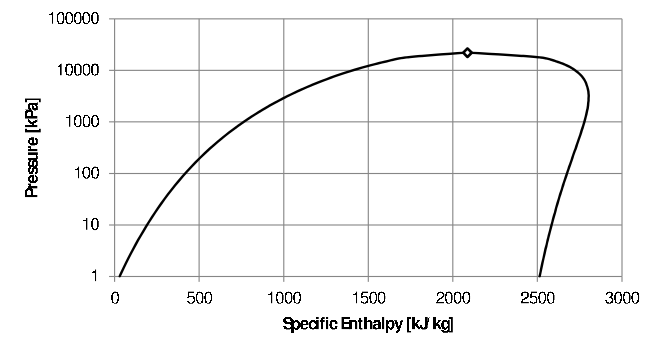
Figure 5.1: Pressure-Specific Enthalpy diagram for water.
5.1.4 Compressed liquids and solids
Because of the small value of \(v\) for liquids and solids, the \(Pv\) term Equation (5.1) is much smaller than \(u\). As the internal energy of solids and liquids changes very little with pressure anyway, the change in enthalpy with pressure is also small and it can be assumed that the enthalpy of a compressed liquid (and solid) is the same as that of a saturated liquid (and solid) at the same temperature - as long as the difference between the pressure and the saturation pressure at that temperature is not too large.
To simplify matters even further, constant specific heats are usually assumed for liquids and solids34 - as long as no phase change takes place. For compressed liquids and solids, the change in enthalpy with a change in temperature can then be calculated using Equation (5.5). The value of the specific heats for solids and liquids are available in literature (Sonntag and Borgnakke 2012 Table A.3)35
5.2 The first law for steady state, open systems
Consider an open system with mass flowing in and out of the system. The the volume of the system stays constant which is the case with a rigid vessel. If the conditions inside the system boundaries do not change with time36 the specific volume inside will not change and the mass inside the system boundary (\(m=\frac{V}{v}\)) will also stay constant. Therefore, the rate (in \(kg/s\)) at which mass flows into the system, will be the same as the rate of mass flow out of the system. If there are more than one stream in and/or out:
\[\Sigma \dot m_{in}=\Sigma \dot m_{out}\]
In order to calculate the mass flow rate from the average flow velocity (\(\overline{V}\)) and cross sectional area (\(A\)) of the inlet or outlet pipe, the following equations are useful. It states that the volumetric flow rate is equal to the mass flow rate times the specific volume and also equal to the average flow velocity times the area of the pipe (perpendicular to the flow direction): \[\dot{q} \left[\frac{m^3}{s}\right] = \dot{m} v \left[\frac{kg}{s}\frac{m^3}{kg}\right] = \overline{V}A \left[\frac{m}{s} m^2\right]\]
If the state and flow-rate of the streams leaving and entering the system also does not change with time, it is called steady state system and according to the principle of conservation of energy, the First Law, the rate at which energy is entering the system, will be equal to the rate at which energy flows out of the system. The rate at which energy flows is given in \(kJ/sec\) or \(kW\).
We have encountered several forms of energy up to this point: enthalpy, work, heat, potential and kinetic energy. Consider an adiabatic system where work is performed and the changes in kinetic and potential energy can be ignored.
5.2.1 Shaft work
In a closed system, boundary work is performed – usually in a piston-cylinder arrangement. By connecting the piston to a crankshaft as in an internal combustion engine of a car, boundary work is used to provide the energy necessary to rotate the crankshaft which in its turn turns the wheels of the car. In the process boundary work is transformed into shaft work. If this process takes place continuously, the shaft will rotate at a certain speed under a certain torque, delivering mechanical power at a certain rate. This is called rate of shaft work or power and the unit is [\(kW\)]. In turbo machines, direct energy transfer between a fluid and the blades attached to the shaft takes place.
Turbines convert the enthalpy of the incoming stream into shaft power. For compressible substances (gases), both internal energy and flow energy are converted into work and both temperature and pressure will decrease.37 In the case of gas and steam turbines, heat loss is prevented as far as possible because energy lost as heat cannot be converted into work. The rate of heat loss is therefore usually small in comparison to the rate at which energy enters and leaves the system with the fluid and unless otherwise stated, turbines are assumed to be adiabatic. Consider the turbine in Figure 5.2 below.
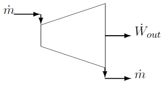
Figure 5.2: Steady state turbine.
The only energy (in the form of internal energy plus flow energy) entering the system is the enthalpy of the inlet stream. It enters the system at a certain mass flow rate \(\dot{m}\) in [\(kg/s\)]. Energy leaves the system as shaft work and also with the outlet stream. Turbines operating at an elevated temperature are usually thermally isolated to prevent heat loss to the environment as energy lost as heat cannot be converted to power and heat loss will therefore decrease the power output. Also the rate at which energy flows through the system \(\dot m\times h\) is most probably much larger than the unavoidable heat loss and therefore we usually assume that turbines are adiabatic. The first law states that the rate at which energy flows IN must equal the rate at which energy flows OUT of the system. In mathematical terms:
\[\dot m h_{in}=\dot m h_{out}+\dot W_{out}\]
The rate of energy transfer is \([kg/s \cdot kJ/kg] = [kJ/s]\) or [\(kW\)]. The "W" stands for Watt. The rate of mechanical energy output \(\dot{W}_{shaft}\) is called power and its unit is also [\(kW\)]. The term work is often used when talking about power. It is technically not correct but the true meaning is usually clear from the context.
Example
Calculate the power delivered by the turbine shaft if the steam at the
inlet of the turbine in the figure above is at \(1MPa\) and
\(500^{\circ}C\). The steam at the outlet is saturated vapour and at
\(5kPa\). The flow-rate is \(20 kg/s\).
Solution
The enthalpy of the steam entering the turbine is
\(3478.44\frac{kJ}{kg}\). The enthalpy of the steam at the outlet is
\(2561.45\frac{kJ}{kg}\). Rearranging the energy balance:
\[\begin{aligned} \dot W_{out} &= \dot m ( h_{in} -h_{out})\\ &= 20(3478.44 - 2561.45)\\ &= 18340 kW \\ \end{aligned}\]
5.2.2 Heat
Heating and cooling are common and important processes. Equipment is often designed in a specific way to maximize the rate of heat transfer. For example, in the radiator of a car, fins are attached to the outside of the water tubes to increase the heat transfer area in order to maximize the heat transfer rate from the water to the air. Sometimes heat is transferred form a heat source to the system. An important example of such a process is the boiler in a power station. Liquid water is fed to the boiler and vaporized to produce steam. Several heat sources can be used but the only primary sources of heat are: chemical (often coal), nuclear radiation (usually the fission of uranium atoms) and solar radiation. Consider the generic heater in the figure below. It is a steady state system. It does not produce any power and changes in kinetic and potential energy are ignored.
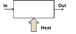
Figure 5.3: Generic heater.
The mass flow rate in is equal to the mass flow rate out of the system. Energy (as internal and flow energy) enters the system with the fluid flowing into the heater. Heat is also supplied to the system. The rate of inflow of energy must equal the rate at which energy flows out of the system. In mathematical terms:
\[\begin{equation} \dot m h_{in}+\dot Q_{in} = \dot m h_{out} \tag{5.6} \end{equation}\]
Example
In a solar water heater, domestic water at \(25^\circ C\) and \(300kPa\) is
pumped through a solar collector. The water must be heated to
\(55^\circ C\). In the collector, heat (from the sun) is delivered at a
rate of \(1.2kW\) to the water. At what rate must the water be pumped
through the collector to ensure the stated outlet temperature? A typical
household geyser holds \(150\ell\) water. How long will it take to heat up
the geyser from \(25^\circ C\) to \(55^\circ C\)?
Solution
Rearranging Equation (5.6) and getting the values for enthalpy from the
saturated liquid tables at the corresponding temperatures:
\[\begin{aligned} \dot m &= \frac{\dot Q_{in}}{h_{in} -h_{out}}&\\ &= \frac{1.2}{230.2-104.87}\frac{kg}{s}\times \frac{60s}{min}&\\ &=0.5745\frac{kg}{min}&\\ \end{aligned}\]
This is approximately two cups of water a minute. The time necessary to heat up \(150\ell\) of cold water (assuming \(1kg=1\ell\)):
\[t=150kg\times\frac{min}{0.5745kg}\times\frac{hr}{60min}=4.35h\]
In general, kinetic and potential energy are also included in formulations of the First Law, which then becomes:(Assuming that heat is added to the system and power is delivered by the system.) Note that the kinetic energy term (\(\frac{1}{2}\dot{m}\overline V^2\)) as well as the potential energy term (\(\dot m g Z\)) are divided by \(1000\) to ensure their units are \(kW\). \[\dot{Q}_{in} + \sum \dot{m} \left(h_{in} + \frac{\overline{\bf V}_{in}^2}{2000} + \frac{gZ_{in}}{1000} \right) = \dot{W}_{out} + \sum \dot{m} \left( h_{out} + \frac{\overline{\bf V}_{out}^2}{2000} + \frac{gZ_{out}}{1000} \right)\]
5.2.3 Kinetic energy
While the change in kinetic energy through a system is often low and therefore usually ignored, there are instances where it is obviously important – for instance jet engines and rockets. Consider a rocket propelled by the gases produced by the combustion of the rocket fuel. The higher the velocity of the exhaust gases, the faster the rocket will travel. In a rocket, a diverging nozzle is employed to convert as much as possible of the enthalpy of the exhaust gases into kinetic energy to maximize the velocity of the rocket. In the process the temperature and pressure of the exhaust gas drop. The ideal is that the pressure of the exhaust gases at the exit of the nozzle is equal to ambient.
Example
Consider a rocket propelled by high pressure air. The air at the inlet
to the nozzle is at \(300K\) and \(295.7kPa\) and at the outlet of the
nozzle the temperature dropped to \(240K\) and the pressure to \(100kPa\).
Determine the velocity of the air at the outlet of the nozzle. It can be
assumed that the inlet velocity is negligible.
Solution
The heat loss will be very small compared to the rate at which energy
flows through the nozzle and therefore it is assumed that the nozzle is
adiabatic. The nozzle does not produce work. Ignoring the change in
elevation (see next paragraph) and letting \(\dot m =1 \frac{kg}{s}\),
an energy balance over the nozzle simplifies to:
\[h_{in}=h_{out}+\frac{\overline V^2_{out}}{2000}\]
Getting the values for enthalpy from the table (Sonntag and Borgnakke 2012 Table A 7.1) enables us to calculate the velocity at the outlet of the nozzle:
\[\overline V_{out}=\left(2000(300.47-240.27)\right)^{\frac{1}{2}}=353\frac{m}{s}\]
Under the assumption of ideal gas behaviour, pressures are irrelevant here. They are however necessary to calculate the maximum possible outlet velocity for the same inlet conditions and outlet pressure by making use of the concept of an "ideal" nozzle.
5.2.4 Potential energy
In thermal-fluid devices such as steam turbines, compressors and heat exchangers, the change in elevation around the device is in the order of meters (if not zero) and the change in potential energy is generally much smaller than the change in the other terms in an energy balance. Therefore the change in potential energy can safely be ignored especially with low density working fluids such as steam and other gases. The density of liquids is much higher and when the change in elevation is significant, the change in potential energy is important – for instance when water is pumped from a lower elevation to a higher elevation – as in a bore hole38 or with the generation of hydro-electric power.
Consider the Drakensberg pumped storage scheme. During times of low electricity demand, water is pumped from the Kilburn dam (water surface 1256 m above sea level) to the Driekloof dam (water surface 1702 m above sea level). In the electricity generating mode, water flows back from the Driekloof dam through the turbines to the Kilburn dam. The flow rate when generating electricity is \(312m^3/s\). Assuming frictionless flow and zero turbulence, calculate the power output of the turbines.
Let us take point 1 as the surface of the Driekloof dam and point 2 as the surface of the Kilburn dam and apply the First Law between these two points. Separating enthalpy into its terms the First Law now becomes:
\[u_1+{P_1}{v_1}+\frac{{\bf \overline V}_1^2}{2000}+\frac{gZ_1}{1000}+\dot q_{in}=u_2+ {P_2}{v_2} +\frac{{\bf \overline V}_2^2}{2000}+\frac{gZ_2}{1000}+\dot w_{out}\]
If we assume water is incompressible, the internal energy of the water will not change when it passes without friction or turbulence through the turbine and piping (see Paragraph 6.7). Therefore \(u_1=u_2\). Because of the small value of \(v\), the \(Pv\) terms are small. Furthermore, the pressures at the two dam surfaces does not differ much. The pressure of the water at each dam surface is equal to the ambient pressure. Assume the ambient pressure at the Kilburn dam is \(100kPa\). Assuming a density of air of \(1kg/m^3\) the ambient pressure at the surface of the Driekloof dam can be calculated as \(95.6kPa\). Because of the small change in ambient pressure and the small value of \(v\), the \(Pv\) terms are ignored. The water will essentially be at the same temperature as the rock and therefore it can be assumed that the rate of heat loss (or gain) of the water will be much less than the rate energy is passing through the pipe (\(\dot m h\)) and that the process is therefore adiabatic. The water at the surface of each dam is also stationary so there is no change in kinetic energy.
The First Law between the surfaces of the Driekloof and Kilburn dams now becomes:
\[\dot{W}_{out} = \frac{ \dot{m} g }{1000} \left({Z_{Driekloof}-Z_{Kilburn}} \right)=1365MW\]
Note the high water mass flow-rate (\(312\thinspace000kg/s \thinspace @ \thinspace 0.001m^3/kg\))39 and the huge change in elevation (\(446m\)) necessary before a significant amount (on a national scale) of power is delivered.40
5.2.5 Common open systems
Because open systems are so varied, it is usually the best practice to formulate the First Law for each individual case. All the energy terms entering the system are written down and set equal to all the energy terms leaving the system. In the examples below, kinetic and potential energies are ignored. This may not be always valid. (See note at the end of this paragraph.)
Just as energy is conserved, mass is also conserved. If there are more than one inlet and/or outlet stream, care must be taken to take all streams into account
5.2.5.1 Valves
Valves are used to control flow rate or reduce pressure. Valves do not perform work. The rate at which energy flows through the valve \(\dot{m} h\) is much larger than any heat loss or gain by the substance as it passes through the valve. Therefore a valve is usually assumed to be adiabatic.
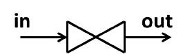
Figure 5.4: Valve.
Therefore: \[h_{in} = h_{out}\]
5.2.5.2 Compressors/pumps
A compressor is used to raise the pressure of a gas and a pump to raise the pressure of a liquid. Both require power to accomplish this. Unless stated otherwise, compressors and pumps are assumed to be adiabatic.

Figure 5.5: Compressor and pump.
An energy balance gives:
\[\dot{m}h_{in} + \dot{W}_{in} = \dot{m}h_{out}\]
5.2.6 Condenser
In a condenser, heat is removed and a vapour turned into a liquid. A condenser does not perform or require power.
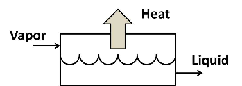
Figure 5.6: Condenser.
An energy balance gives: \[\dot{m}h_{vapor} = \dot{m}h_{liquid} + \dot{Q}_{out}\]
5.2.6.1 Evaporator / Boiler
Liquid flows to an evaporator and is evaporated by the addition of heat as shown in Figure 5.3. In power stations steam is produced in boilers from high pressure liquid water. Usually the steam is also significantly super-heated before leaving the boiler. An energy balance (from Figure 5.3) gives:
\[\dot{m}h_{liquid} + \dot{Q}_{in} = \dot{m}h_{vapor}\]
5.2.6.2 Heat exchanger
In a heat exchanger heat is transferred from a hot fluid to a colder fluid without the two fluids mixing. An example is the radiator of a car where the water releases heat to the ambient air and returns to the engine. The two fluids are separated by a conducting medium (usually a metal). A schematic presentation of a counterflow heat exchanger is shown in Figure 5.7. Also shown in Figure 5.7, is an often used symbol for a heat exchanger.
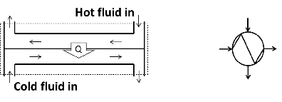
Figure 5.7: heat exchanger.
The system boundary is shown as a dotted line in Figure 5.7. Doing an energy balance over the system boundary, results in the equation below. It is assumed that the rate at which heat is exchanged between the two streams is much larger than possible heat exchange between any (or both) of the streams and the environment and this exchange with the environment is therefore ignored.
\[\dot{m}_h h_h|_{in} + \dot{m}_c h_c|_{in} = \dot{m}_h h_h|_{out} + \dot{m}_c h_c|_{out}\]
Note that the rate of energy transfer (\(\dot Q\)) does not appear in the energy balance because it does not cross the system boundary.
Note: It is usually assumed that kinetic and potential energy are negligible or that turbines and compressors are adiabatic. These assumptions has been stated in the discussion of the different systems and will not be mentioned again in problem statements. It will be clear from the problem statement whether (for instance) kinetic energy must be taken into consideration. Usually, if nothing is said, it can be assumed that the usual assumptions are valid.
5.3 Unsteady state processes
Many important processes are not steady state. If a pressure vessel springs a major leak, it is important to know how the temperature and pressure inside will change with time. Filling a closed tank with a gas or a liquid is another example of unsteady state processes. A general unsteady state process with a single inlet and outlet is shown in the figure below:
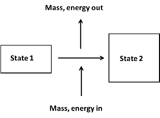
Figure 5.8: Unsteady state process.
Unlike steady state processes, the amount of mass inside the system boundary does change during an unsteady state process. Like energy, mass is also conserved and a mass balance for the process (single inlet and single outlet stream) in Figure 5.8 are:
\[m_1 + \Sigma m_{in} = \Sigma m_{out} + m_2\]
Note that in general more than one stream can flow into and more than one stream can flow out of the system. Assuming a stationary system an energy balance for an general unsteady state process can be written as:
\[m_1 u_1 + \Sigma ({{m} h})_{in} + \Sigma{E}_{{in}}= m_2 u_2+\Sigma ({{m} h})_{out}+\Sigma{E}_{{out}}\]
Where E accounts for all the other forms of energy: heat, boundary and shaft work and kinetic energy. The summation signs are used as more than one stream can flow into and more than one stream can flow out of the system. Note that the initial and final mass as well as the mass in (or out) is in \([kg]\). Even though there may be flow across the systems boundary, it is an amount of substance that flows. The unit of all the \(mu\) and \(mh\) terms (and therefore also for heat an work) in the energy balance equation is therefore:
\[kg\times\frac{kJ}{kg}=kJ\]
Example
Consider a rigid tank of \(2m^3\) containing pressurized air at \(400kPa\)
and \(25^\circ C\). The tank slowly deflates through a small hole in the
tank wall. Due to the loss of air, the pressure drops to \(100kPa\) and
due to heat transfer with the environment, the temperature of the air in
the tank remains on \(25^\circ C\). Calculate the the heat transfer.
Solution
Assuming the tank releases heat to the environment, the energy balance
becomes: \[m_1u_1 = m_2 u_2 + m_{out}h_{out}+ Q_{out}\] (As the tank is
rigid, its volume remains constant and no boundary work is done. It goes
without saying that there is no shaft work as there is no turbine or
compressor. As nothing is said in the problem statement, it is also
assumed that the potential and kinetic energy do not chance.) From a
mass balance it is clear that \(m_1=m_2+m_{out}\). The air leaking from
the vessel will be at \(25^\circ C\) and the heat transfer can be
calculated:
\[Q_{out}=9.35\times 213.04-2.34\times 213.04-7.01\times298.62=-600kJ\]
As the the value of \(Q_{out}\) is negative it means that our assumption that the tank releases heat is wrong and that heat in actual fact flows from the environment to the tank and the answer is reported as: \[Q_{in}=600kJ\]
5.3.1 Quantity and rate
The amount (or quantity) of energy of a component in a closed system is given by the mass of the component multiplied by the internal energy: \(E = m \times u\). Typically the energy in the system before a process has taken place (the energy in the beginning) is: \(m_1u_1\). \(m_1\) is the amount of the component in the system and \(m_1u_1\) is the amount of energy in \(kJ\). (\([kg][\frac{kJ}{kg}]=kJ\)).
The energy content of a material that flows has two components: the internal energy (\(u\)) and the flow energy (\(Pv\)). These two are combined in the property, enthalpy. If an amount of a component (one kilogram of air, two kilograms of steam) cross the system boundary in an unsteady state process, a certain amount of energy (associated with this component) cross the system boundary: \(m\times h\) and the units is again \(kJ\). All terms in the energy balance must have the same units. Therefore the heat transfer and work terms will also have units of \([kJ]\).
If a component flows at a certain rate (\(\dot m\)) through a pipe, energy also “flows” at a certain rate through the pipe: \(\dot m \times h\), and the units is \(kW\) (\([\frac{kg}{s}][\frac{kJ}{kg}]=\frac{kJ}{s}=kW\)). In steady state open systems the unit for heat transfer rate and power is therefore also \([kW]\).
These two concepts \(kJ\) and \(kW\) can also be be explained using IT terminology.
The Byte was originally developed to store a single alphanumeric character. In order to store the word \(Thermodynamics\) will therefore require 14 Bytes of computer memory. The capacity of data storage devices is measured in Bytes. If we say a flash drive has a capacity of 32MB, it means it can store \(32\times 10^6\) Bytes of data. The PDF file containing this notes is 1.6 MB.
In the same manner, a \(Joule\) is the unit used when measuring the amount of energy. A teaspoon of sugar contains approximately \(70 kJ\) dietary energy. In Chapter 3 we also used \(kJ\) as the unit to measure the amount of heat energy necessary to raise the temperature of a substance or the magnitude of work.
Returning to data again. The data transfer rate is given in Bytes per second abbreviated as \(Bps\). Again this unit is too small as data is usually transferred quite fast. The data transfer rate (or speed) of a typical domestic internet connection is 2MBps. This means it will take 0.8 seconds to download this notes. (Note that 1MBytes per second = 8Mbits per second but explaining that is beyond the scope of this discussion.)
In the same manner the rate of energy transfer is given in Joule per second or \(J/s\). As a \(1 J/s = 1 Watt\) and Watts are usually too small a unit, we use the symbol \(kW\) for the rate of energy transfer. \(1kW=10^3J/s\)
5.4 Calculating heat transfer using specific heats
In general, the First Law is used to calculate the amount of heat transferred during a process. We will now consider the calculation of heat transfer for sub-cooled solids and compressed liquids which are often handy as short-cuts. These short cuts are derived from the First Law. It is therefore good practice to make sure that you have included all the relevant energy terms.
5.4.1 Open Systems
For liquid water (and other liquids) it can safely be assumed that enthalpy is independent of pressure as discussed in Paragraph 1.1.4. The change in enthalpy is therefore given by \(dh=C_pdT\). For liquid water \(C_p\) is not strongly dependent on temperature. Consider the heating of water as in Figure 5.3. Equation (5.6) now becomes:
\[\begin{equation} \dot{Q}_{in}=\dot{m}C_p(T_{out}-T_{in}) \tag{5.7} \end{equation}\]
This equation comes in handy as often only the values of the temperatures are known. For instance, often only the inlet and outlet temperature of cooling water flowing through a heat exchanger are displayed by temperature gauges. In domestic applications, only the inlet and outlet temperatures of the water streams flowing through a geyser or solar water heater or a heat pump may be known.
The Example on page can be done using Equation (5.7) and a value of \(4.183\frac{kJ}{kg\cdot K}\) for the specific heat of water. Using the specific heat to calculate change in enthalpy, results in a \(\Delta h = 125.33 \frac{kJ}{kg}\) while using the values for enthalpy of saturated liquid water (as in the example) results in a value of \(125.49\frac{kJ}{kg}\).
5.4.2 Closed Systems
If a solid or a liquid is heated at constant pressure (for instance a cup of water) the heat transfer can be calculated by using the First Law for a closed system. Assuming a constant specific heat, this gives:
\[\begin{equation} \begin{aligned} Q_{in} &=m((u_2-u_1)+P(v_2-v_1))\\ &=m((u_2+P_2 \times v_2)-(u_1-P_1 \times v_1))\\ &=m(h_2-h_1)\\ &=mC_p(T_2-T_1) \end{aligned} \tag{5.8} \end{equation}\]
The values of \(C_p\) are available in literature. See Table A.3 in the book of Sonntag (Sonntag and Borgnakke 2012) for liquids and Table A.4 (Sonntag and Borgnakke 2012) for solids. The values for \(C_v\) are not listed – for two reasons. Liquids and solids are usually not heated under constant volume conditions because the pressure rises dramatically during heating because of their low compressibility. Secondly, because the specific volume of liquids and solids are small, the \(Pv\) term is much smaller than \(u\) and it is usually assumed that \(C_v=C_p\).
The fact that \(Pv\) (work performed) plays such a small role also means that, for closed systems, in the case of liquids and solids, the type of process becomes irrelevant.
The same approach for the determination of the values of the outstanding properties is followed as described in Paragraph 4.1 for internal energy.↩︎
See Figure 4.1 If \(C_v\) is constant, \(C_p\) is also because \(C_p-C_v=R\)↩︎
The specific heat of liquid water at \(25^\circ\)C and \(100kPa\) is \(4.183 \frac{kJ}{kg \cdot K}\). It stays essentially constant except close to the freezing (\(0^\circ C\)) and boiling point (\(99.6^\circ\)C) where it rises by less than one percent.↩︎
Often no distinction is made between \(C_p\) and \(C_v\) because the work performed when a solid or liquid is heated at constant pressure is small because of the small change in the already small value of specific volume. Therefore the additional heat that must be supplied to compensate for the work performed – over and above the heat necessary to increase the internal energy, will be negligible and their values will be essentially the same.↩︎
The pressure inside a deflating tank will change with time and this is therefore an unsteady system.↩︎
For an incompressible substance no expansion takes place and therefore the molecules cannot transfer their energy to a moving boundary and only flow energy is converted into work and only the pressure will drop. Any change in the internal energy is due to friction and turbulence in the turbine.↩︎
Friction between the flowing fluid and the pipe wall will contribute to the power required by the bore hole pump. Fluid friction is studied in detail in Fluid Mechanics.↩︎
The annual average inflow into the Vaal dam is \(61\thinspace800kg/s\). During the flood of 1996, water was released at a record rate of \(2\thinspace300\thinspace000kg/s\) from the dam. (Source: https://www.dwa.gov.za/Orange/Vaal/vaaldam.aspx)↩︎
Each of the six units of the new Kusile power station is rated at 800MW.↩︎