Introduction to Coordinate Reference System
The coordinate reference system (CRS) is one of the most important functions of GIS. It is a coordinate-based local, regional or global system used to locate geographical features that occupy a position in space, and it allows users to analyse geographic data using accurate locations and measurements.
(Coordinate reference systems and spatial reference system (SRS) are synonyms and are commonly interchanged.)
The two types of coordinate reference system in GIS are:
For example in ArcMap, when a spatial data is created or added, the coordinate or spatial references may need to be set.
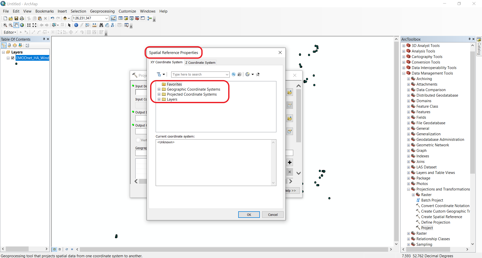
Both geographic coordinate and projected coordinate systems will come with many options.
So let’s discuss what these are separately.
Geographic coordinate system
Geographic coordinate system is used to define locations on the three-dimensional Earth. GCS shows where a certain location is on the surface of the Earth.
Geographic coordinate system is defined by:
Angular units (degrees)
Geodesy
Geodesy is the science associated with the measurement and portrayal of the Earth. Geodesy is used to determine the size and shape of the Earth, as well its features (e.g. mountains) and elements (e.g. terrestrial gravity and tides).
Ellipsoid
Geodesists build simple mathematical models to be able to capture the shape of the Earth and its features. For this, they have adopted the ellipsoid (or spheroid) as the most basic model. This is also referred to as geometric model.
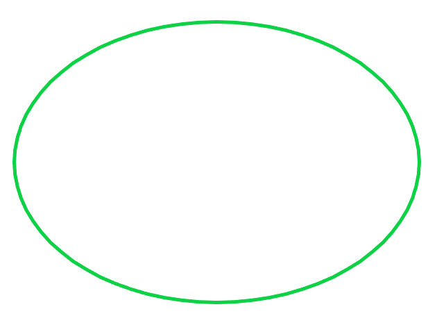
The ellipsoid is an idealised representation of the physical Earth, with a completely smooth, uninterrupted surface.
Note
Since the Earth is spinning around its axis, there is a slight flattening at the poles and a slight bulging at the equator, hence the ellipsoid is used as a model.
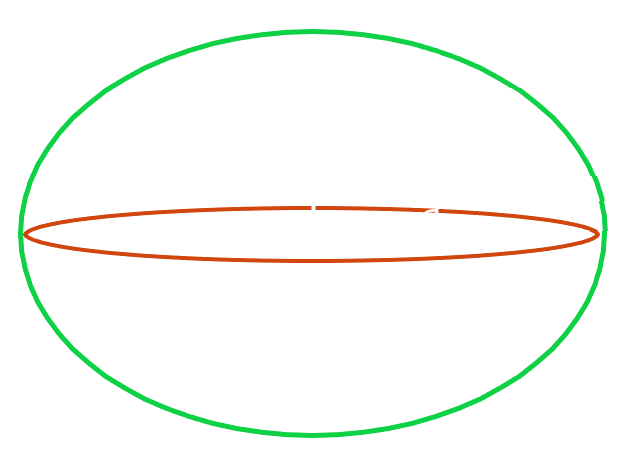
The ellipsoid has a longer semi-major axis (a) and a shorter semi-minor axis (b). The difference between the ellipsoid and the sphere is measured by its flattening (f = (a-b)/a), or the reduction in the minor axis relative to the major axis.
The circumference of the earth is about 1/300th smaller around the poles. This translates to the Earth being around 44km wider than it is tall.
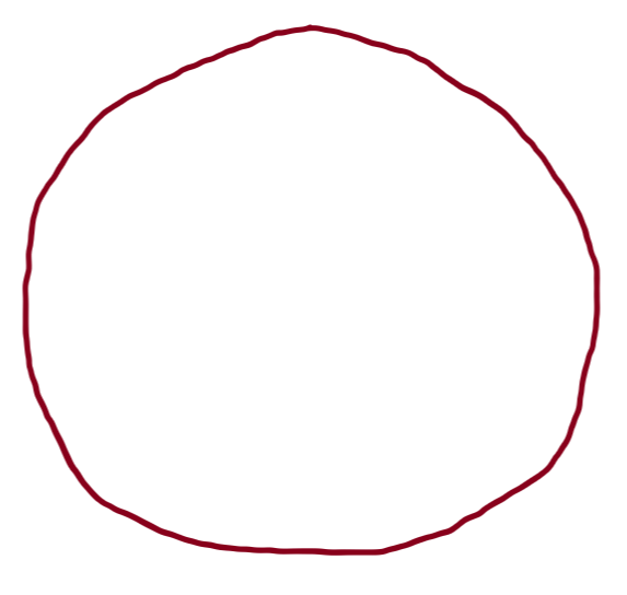
In addition to the flattening and bulging, the different topological features are also account for Earth’s irregular, lumpy shape.
So let’s imagine the modeling process using the ellipsoid.
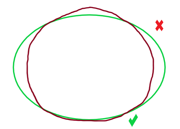
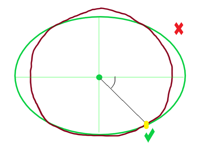
The ellipsoid placed on top of this lumpy shape won’t be able to perfectly model the surface all around. It will only “fit” with the surface at a particular area. This is why the ellipsoid can only be applied at one part of the Earth at the time.
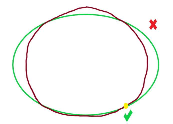
To be able to specify at which part of the planet the ellipsoid is applied to, datums are used.
Datum
Horizontal datums model positions on the surface of the Earth using latitude (y) and longitude (x), while vertical datums are used to model elevations (z) accounting for terrain, bathymetry, water level and man-made structures.
Horizontal datum
A horizontal datum uses a reference ellipsoid that is “pinned” to the Earth at a fixed surface location. This reference location is called marker or benchmark.

and a marker location in Kansas, USA (Source: Wikipedia)
This marker is then used to assign angular units of longitude and latitude to locations at that particular area of the Earth.
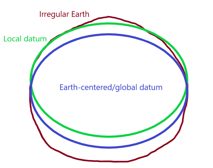
There are different datums designed for different parts of the world. In fact, almost every country has its own datum (local datum). For example, the datum NAD83 (North American Datum 1983) is used to model the North American continent and the NZGD2000 (New Zealand Geodetic Datum 2000) is used for New Zealand and its offshore islands.
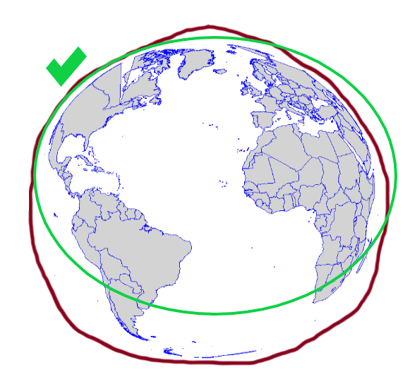
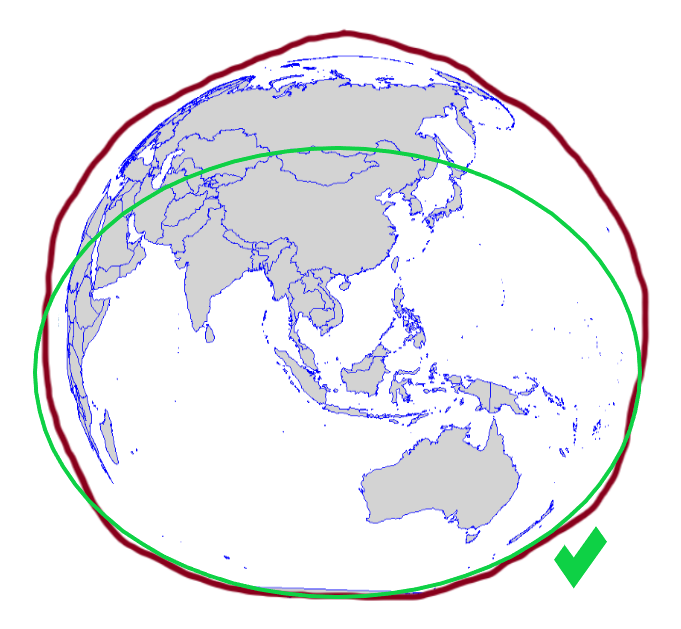
The ellipsoid known as WGS84 or World Geodetic System 84 is the most widely used and well-known datum.
WGS84 is global datum format. It uses the centre of the Earth to connect the ellipsoid and provides a generalised model for the whole of the planet.
Vertical datum
As previously discussed, the shape of the Earth is not perfectly round and its surface is quite uneven: there are different topographic features (e.g. mountains, valleys, trenches). This uneven surface has an effect on Earth’s gravity: higher density rocks will pull water creating a bulge, while water is drawn away from lower density rocks. Thus, gravity is different at different parts of the Earth.
To overcome these gravitational differences, geodesists use the geoid to measure surface elevation. The geoid is also known as gravity-related model.
Removing the effects of the winds and tides, and in fact land masses that cause gravitational differences, the geoid takes the global mean sea level as a base (as if the sea would uniformly cover the planet) to measure surface elevations.
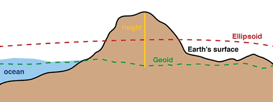
At a certain location, vertical height will be given in reference to the geoid.
The above mentioned WGS84 is used by Global Positioning System (GPS) satellites and can be used globally to obtain latitude, longitude and elevation coordinates at any location. However, at specific areas local datums can still provide better coverage than WGS84. For example, OSGB36 (Ordnance Survey National Grid reference system) is a better approximation to the geoid covering the British Isles than the global WGS84.
Note
Maps made using different datums will give different coordinates for the same position. This is called ‘datum shift’.
The GPS consists of a system of 24 satellites, each orbiting the Earth every 12 hours on distinct orbits at a height of 20,200km and transmitting radio pulses at precisely timed intervals. To determine position, a receiver must make exact calculations from the signals, the known positions of the satellites and the velocity of light. Positioning in three dimensions (y,x,z) requires that at least four satellites are above the horizon and accuracy depends on the number of such satellites and their positions.
GPS is very useful for locating objects that move and for direct capture of the location of fixed objects. However, accuracy will depend on the amount of satellites contributing.
Zoom in and use the tools on the left to interact with the map
Angular units
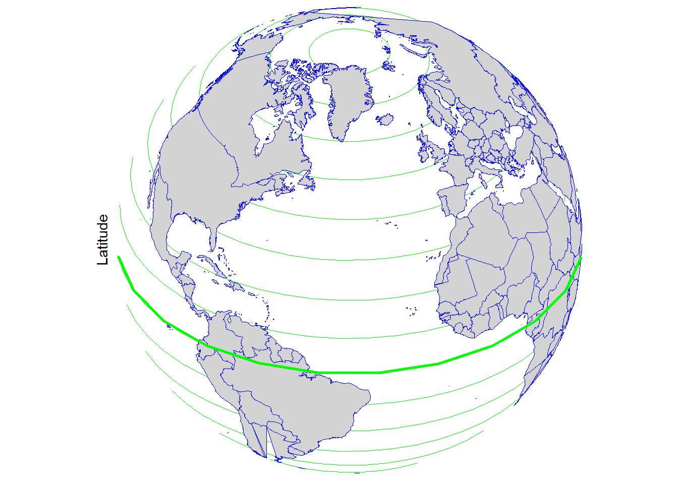
GCS use angular units to describe locations on the Earth’s surface. (Remember, this is based on the ellipsoid and the geoid.) These are the latitude (φ) and longitude (λ) displayed on a spherical coordinate system and are measured in degrees.
Latitude lines run parallel to the equator and divide the Earth into 180 equally spaced sections from north to south.
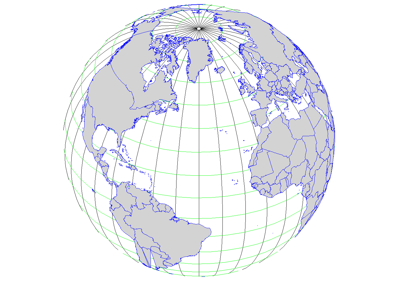
Longitude lines run perpendicular to the equator and converge at the poles. Longitudes are measured from zero to 180 degrees east or west of the prime meridian (0 degrees running through Greenwich, UK).
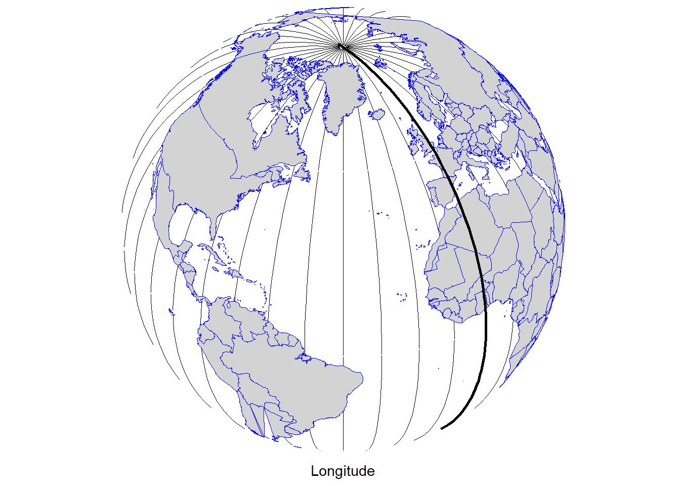
This network of lines representing meridians and parallels are also known as graticules.
The classic representation of latitude and longitude coordinates is in degrees, minutes and seconds (DMS).
The example below shows London on the map with the coordinates displayed in degrees, minutes and seconds.
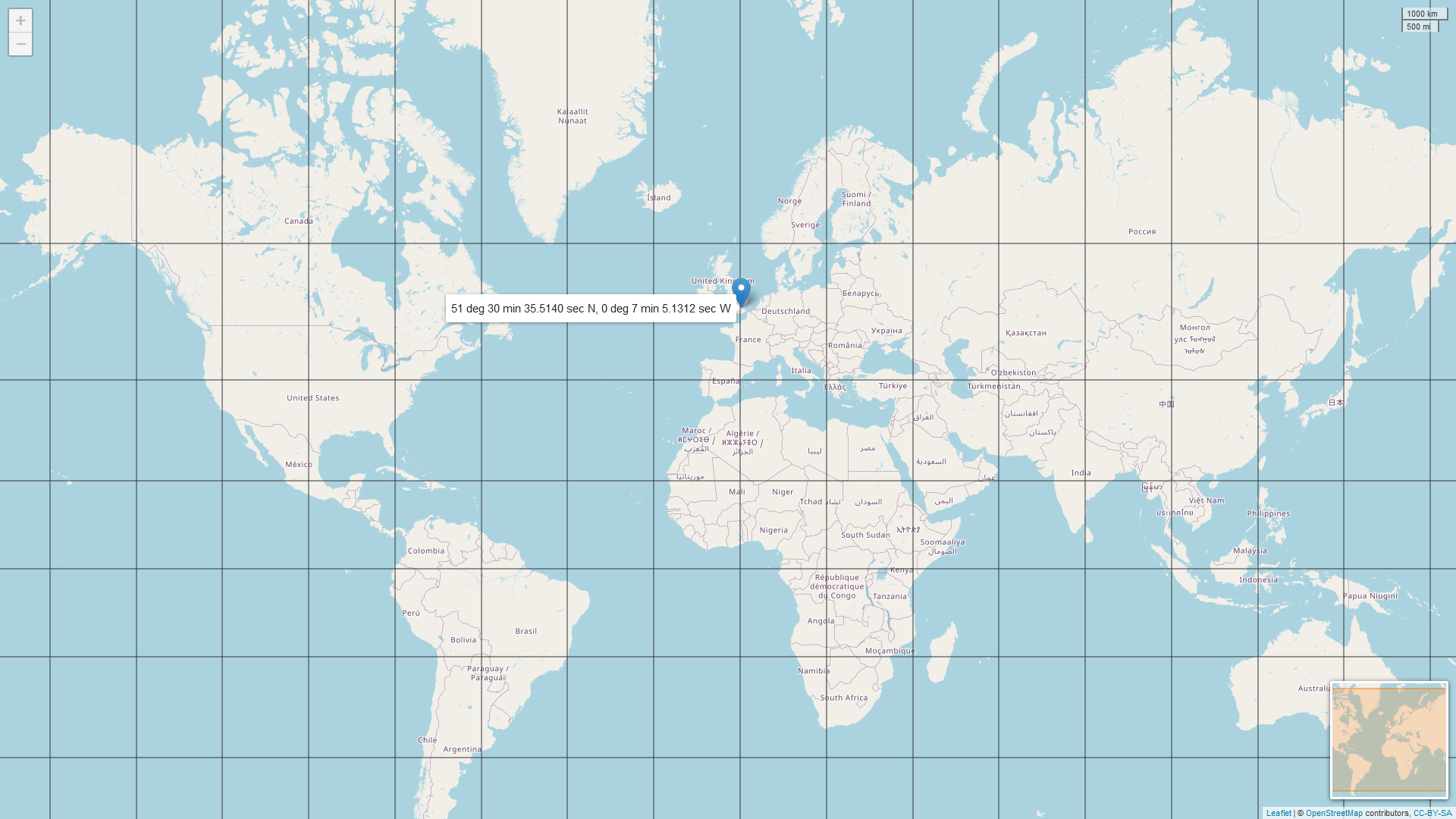
The degrees, minutes and seconds format uses the sexagesimal (base 60) system which is difficult to use in the digital world. Instead, the decimal degrees format (base 10 system) is used. So let’s see how to convert degrees, minutes and seconds to decimal degrees, and decimal degrees to degrees, minutes and seconds.
DMS to DD
| Location | DMS (degrees, minutes and seconds) | DD (decimal degrees) |
|---|---|---|
| London, UK | 51° 30’ 35.5140’’ N, 0° 7’ 5.1312’’ W | ??? |
Leaving the degree value untouched, divide the minute with 60 and the second with 3600. Then, add them up (degree + minute + second). The final value will be the decimal degrees format.
Let’s take the latitude and latitude values separately from the above example.
Latitude: 51 degrees 30 minutes 35.5140 seconds
D (51 degrees) + M (30/60) + S (35.5140/3600) = 51.509865°
Longitude: 0 degrees 7 minutes 5.1312 seconds
D (0 degrees) + M (7/60) + S (5.1312/3600) = 0.118092°
| Location | DMS (degrees, minutes and seconds) | DD (decimal degrees) |
|---|---|---|
| London, UK | 51° 30’ 35.5140’’ N, 0° 7’ 5.1312’’ W | 51.509865°, 0.11809° |
DD to DMS
Here, let’s take the latitude example only.
Latitude: 51.509865
1, The degree value remains the same:
Degrees = 51
2, The decimal value gets multiplied by 60 and the minute will be the number before the decimal separator:
0.509865 x 60 = 30.5919
Minutes = 30
3, The remaining number after the decimal separator gets multiplied by 60 as well. This will give the second.
0.5919 x 60 = 35.514
Seconds = 35.514
51° 30’ 35.514’’
When using DMS and DD, directions are specified by using N, E, S and W or +/-, respectively (i.e. y above the equator and x east of the prime meridian are positive, and y below the equator and x west of the prime meridian are negative).
Apart from DMS and DD, there is also a third format to display locations. This is called degrees decimal minutes (DDM).
Degrees, minutes and seconds can also be converted to degrees decimal minutes.
DMS to DDM
Using the same example, starting from the back:
Latitude: 51 degrees 30 minutes 35.5140 seconds
1, Divide the seconds by 60:
35.5140/60 = 0.5919
2, Add the minute:
30 + 0.5919 = 30.5919
3, The degree value remains the same:
51°30.5919’
Longitude: 0 degrees 7 minutes 5.1312 seconds
0°7.08552’
| Location | DMS (degrees, minutes and seconds) | DD (decimal degrees) | DDM (degrees decimal minutes) |
|---|---|---|---|
| London, UK | 51° 30’ 35.5140’’ N, 0° 7’ 5.1312’’ W | 51.509865°, 0.11809° | 51°30.5919’, 0°7.08552’ |
Tip
The website PGC Coordinate Converter is useful to convert all three formats.
Batch Convert Tool allows to convert UK Grid Reference, easting and northing, and decimal degrees formats.
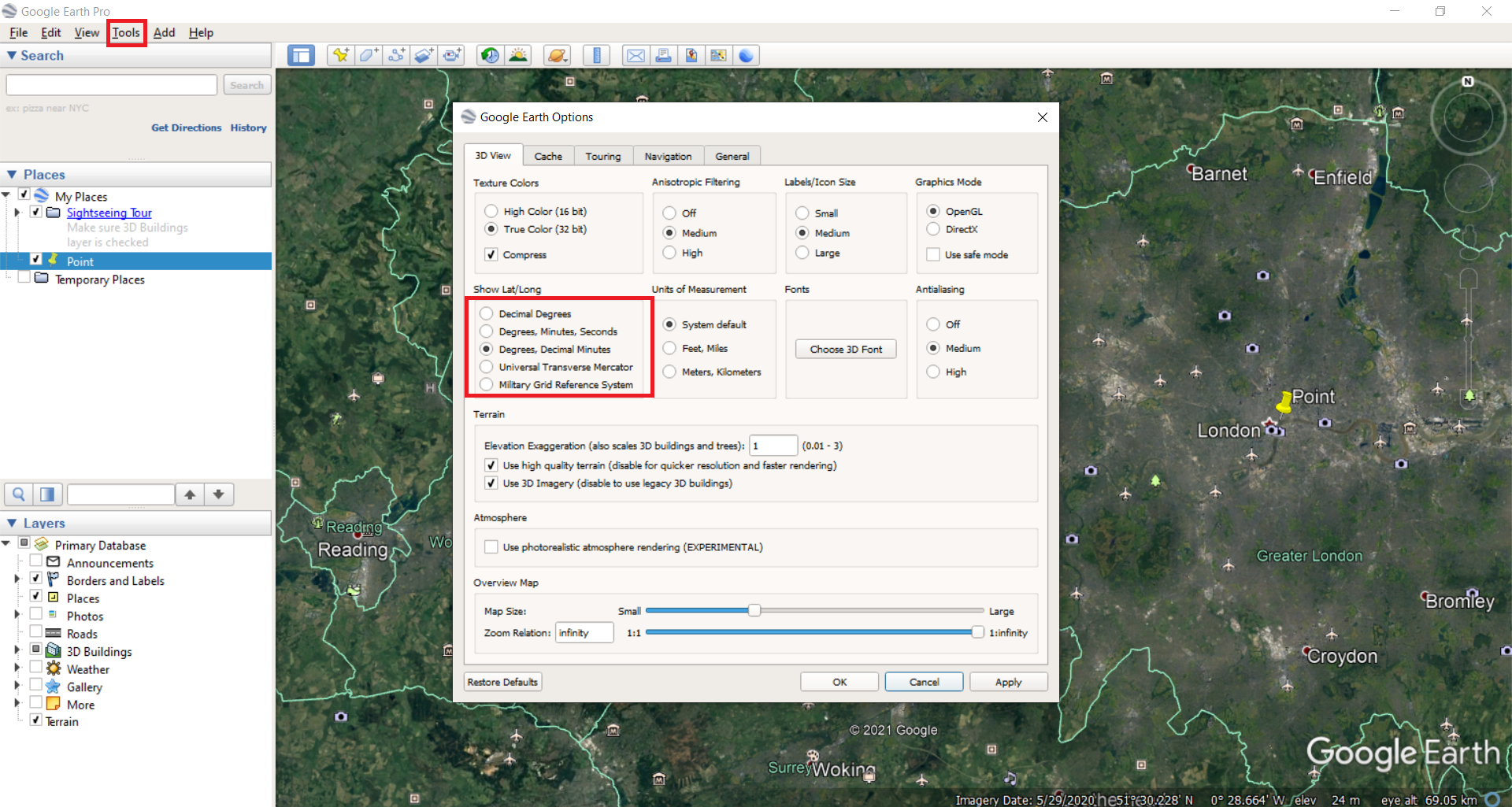
Google Earth Pro also gives the option to display and convert all formats (Tools –> Options).
Distance
As mentioned before, latitude and longitude are applied to the three-dimensional Earth to describe location. However, they are not very useful to measure linear distances. This is because of the oblate spheroid shape of the Earth.
Latitude lines are concentric circles that become smaller near the poles while the distance between them remains roughly the same. (The distance between two degrees is slightly bigger at the poles than at the equator because of the flattening. The average distance between two latitude degrees is 111km. One minute of latitude is 1.86km which equals one nautical mile.)
| Latitude | Poles | 80° N/S | 40° N/S | Equator |
|---|---|---|---|---|
| Distance between two degrees | 111.69km | 111.66km | 111.03km | 110.57km |
Longitude lines converge at the poles and thus the distance between two meridians is different at every parallel.
| Longitude | Poles | 80° N/S | 40° N/S | Equator |
|---|---|---|---|---|
| Distance between two degrees | - | 19.39km | 85.39km | 111.32km |
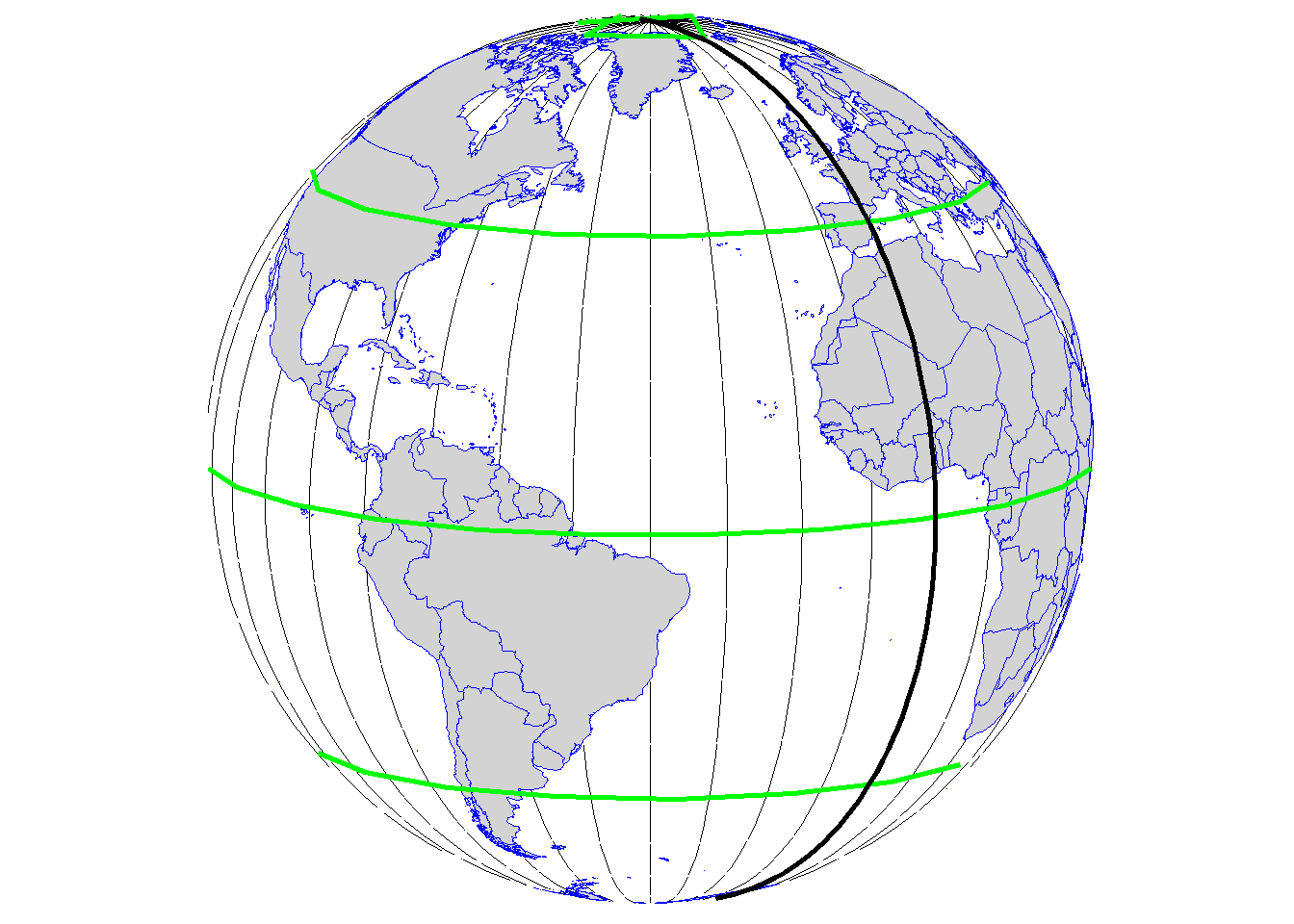
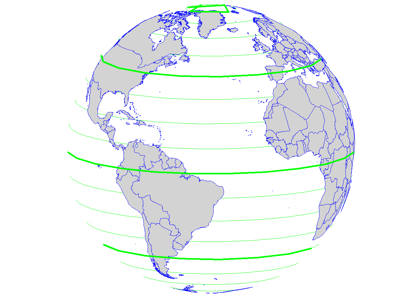
The equator is the only place where the linear distance corresponding to one degree latitude is approximately equal the distance corresponding to one degree longitude. (Note that the illustration below shows the latitude and longitude lines at every 10° for easier visualisation.)

Note
Formula to calculate distances at one minute latitude and at one second latitude at the equator:
1°= 110.57km
1’ = 110.57/60 = 1.84283km
1’’ = 1.84283/60 = 30.7138m
The same formula applies at one degree/minute/second at all latitude and longitude lines, except at the poles where the longitude lines converge.
Interesting fact
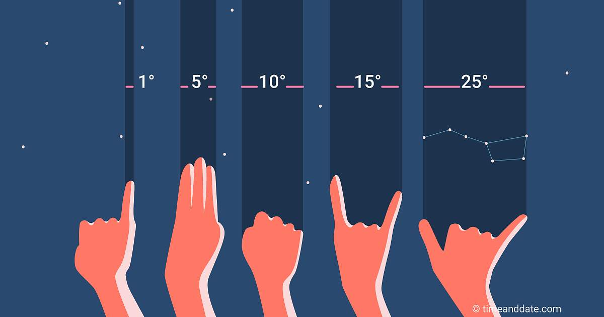
Measuring distance on the sky
When holding out one hand at arm’s length with one eye closed:
The little finger at an arms length is about 1° wide.
Three middle fingers spans about 5°.
The width of a fist is approximately 10°.
The tip-to-tip span between the index and little finger is 15°.
The tip-to-tip span between the thumb and little finger is 25°.
Note
24 hours equals with Earth’s full rotation around its axis (360°).
In one hour, Earth turns 15°.
In every four minutes, Earth turns one degree.
Direction
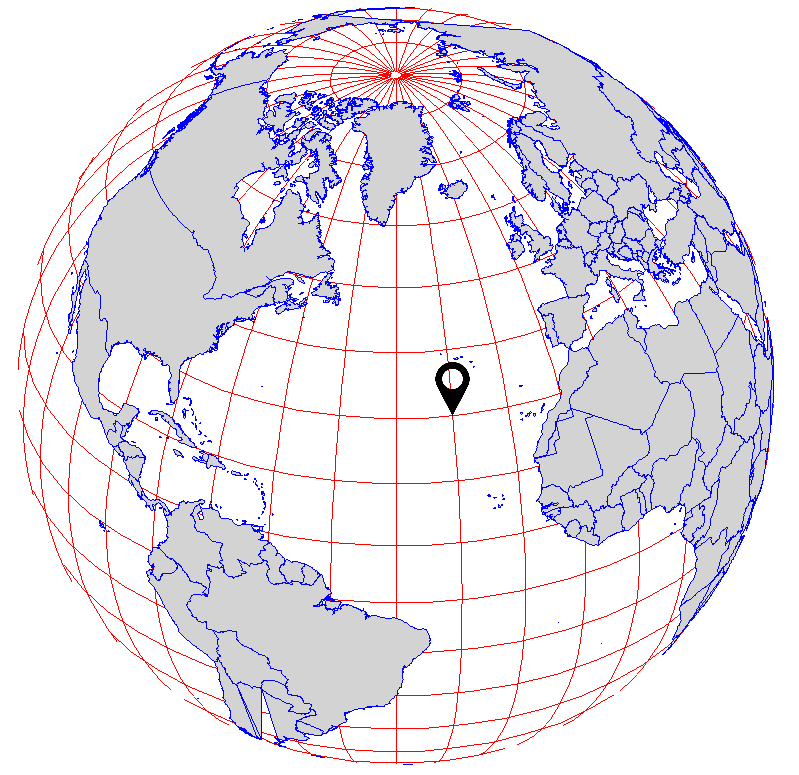
Maps tend to show a straight line as a shortest distance between two points.
However, on spherical Earth this is not the case. Instead, this is better illustrated with an arced line, called great circle, that shows the shortest distance between two points on a sphere.
Long-distance air traffic uses great circle routes routinely, plotting great circles to fly the shortest distance between two locations.
The video below explains and visualises the concept of great circles and straight lines really well.
This issue of distance and direction at different latitude and longitude is bridged and accounted for by most GIS software and discussed in the projected coordinate system section below.
Projected coordinate system
Whilst GCS shows where a certain location is on the Earth’s surface, the projected coordinate system (PCS) shows how the three-dimensional Earth should be projected on a two-dimensional flat surface to accurately display that same location.
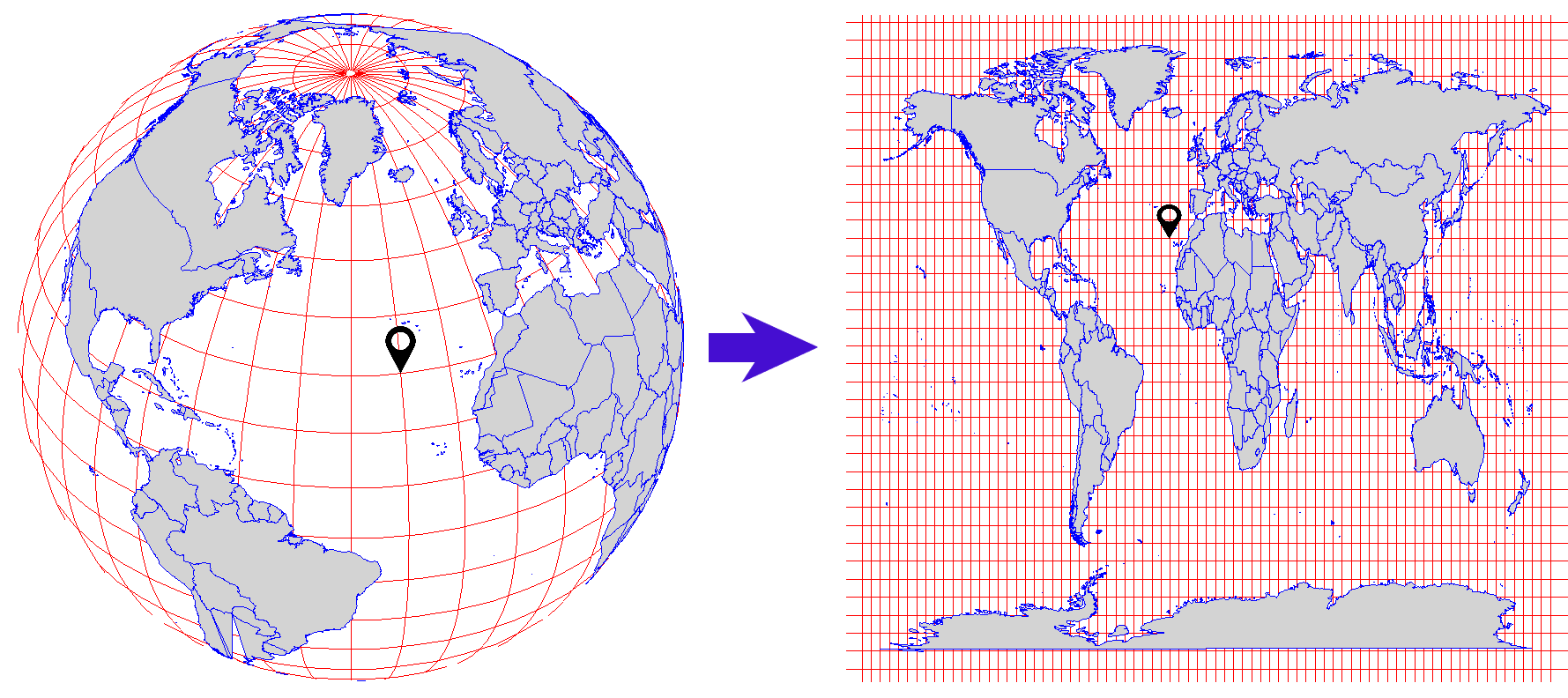
Map projection
The transformation used to convert the three-dimensional spherical Earth onto a two-dimensional flat surface is referred to as a map projection. A map projection uses mathematical formulas to relate spherical coordinates on the globe to planar coordinates using the Cartesian coordinate system.
Cartesian coordinate system
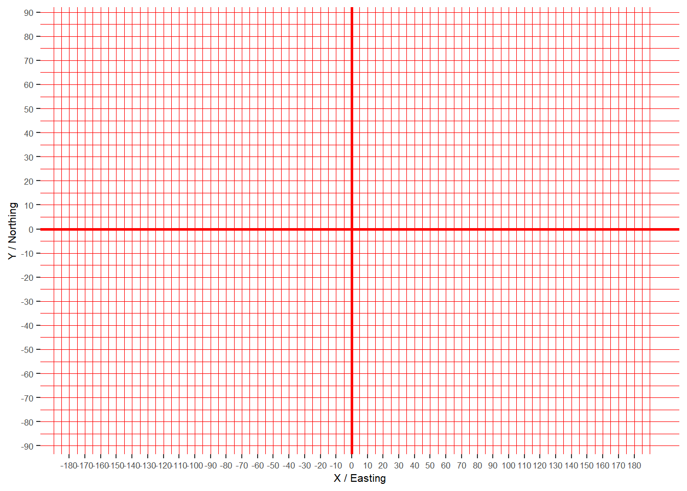
The Cartesian coordinate system assigns two coordinates to every point on a flat surface by measuring distances from an origin parallel to two axes drawn at right angles:
Horizontal (X / Easting) axis runs from east to west, ranging from +180° to -180°.
Vertical (y / Northing) axis runs from north to south, ranging from +90° to -90°.
The point at which the axes intersect is called the origin (0,0). Locations are defined relative to the origin, using the notation (x,y).
When working with data in a geographic coordinate system, longitude values are equated with the X axis and the latitude values are equated with the Y axis.
Projection types
As it was discussed in the Introduction to Cartography chapter, during the map projection process distortion occurs affecting shape, area, distance and direction. Depending on the on the map’s content and purpose, different projection types and methods are used to minimalise distortion.
The three projection types are:
- Cylindrical (normal, transverse, oblique)
These projections are used for the entire earth and for areas at the equator.
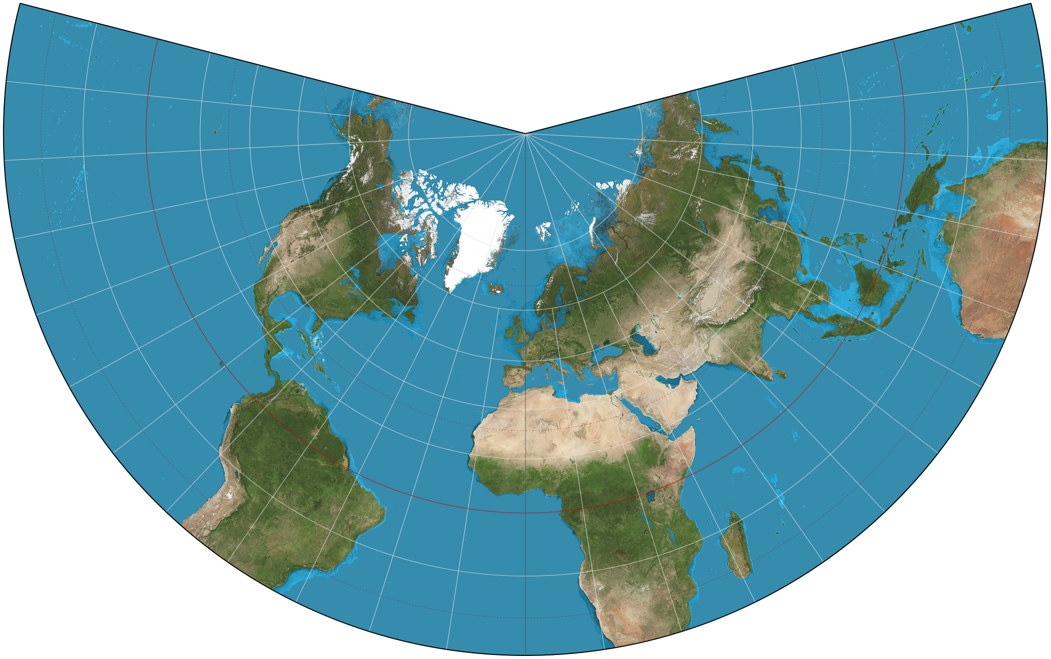
- Conical (secant, tangent)
These projections are used for the mid-latitudes.
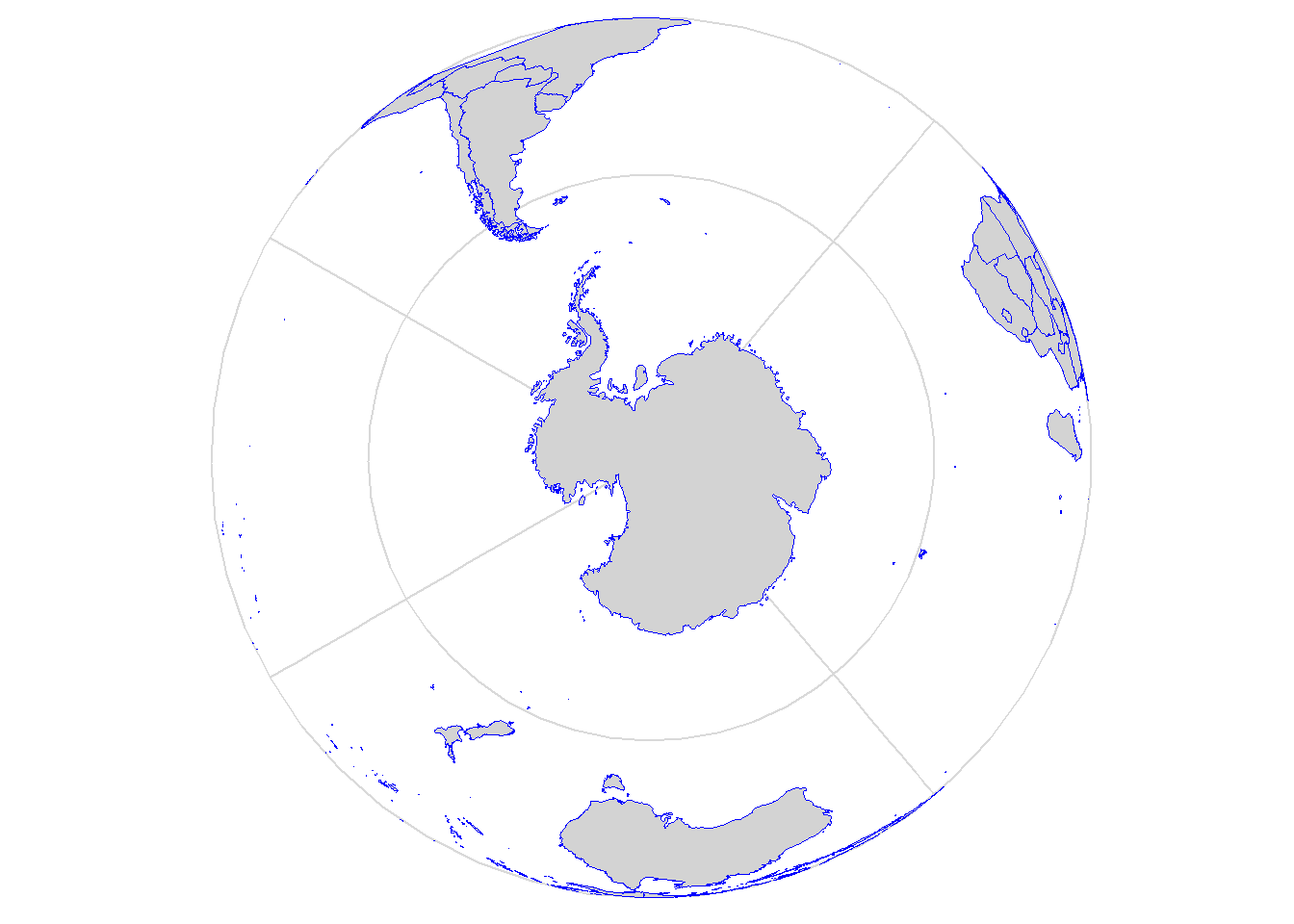
- Planar/Azimuthal (Gnomonic, Stereographic, Orthographic)
These projections are used for the poles.

Projection methods
Within the projection types, there are different kind of methods used. The most commons are:
Lambert Conformal Conic
Lambert Conformal Conic is used for aeronautical charts, portions of the State Plane Coordinate System, and many national and regional mapping systems. It is also one of the best projection methods for middle latitudes.
Azimuthal Equal Area
This projection maintains land features at their true relative sizes while simultaneously maintaining a true sense of direction from the center. It is best suited for individual land masses that are symmetrically proportioned, either round or square.
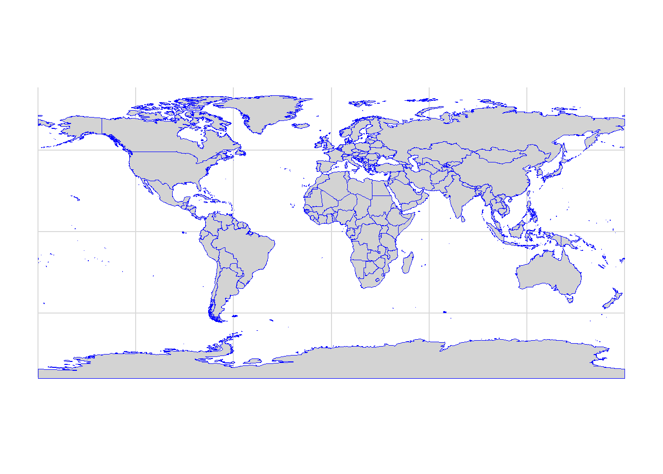
Equidistant Cylindrical (Plate Carrée)
This projection is neither equal-area nor conformal. One of the simplest of all map projections and one of the oldest.
There are also projection methods that use their own coordinate system.
Universal Transverse Mercator (UTM)
UTM is based on the Mercator projection, but in the transverse rather than equatorial aspect: like wrapping a cylinder around the poles rather than around the equator.
UTM divides the world into 60 grids that are all 6 degrees wide in longitude.
Each grid has a central meridian of 500,000m and each is segmented into 20 latitude bands that are 8 degrees high.
Along the latitude lines, each grid lettered starting from C at 80°S, increasing until X (English alphabet), omitting the letters I and O. The last latitude band, X is extended an extra 4 degrees ending at 84°N latitude, thus covering the northernmost land on Earth. Latitude bands A and B, and Y and Z bands cover the western and eastern sides of the Antarctic and Arctic regions respectively.
Each grid is also divided into north (N) and south (S) depending on its location from the equator.
Hover over the map
Using the UTM coordinate system, a location will be defined by the following parameters:
UTM zone number and letter
Northing (Y) value which is the distance of the point from the equator, given in metres.
Easting (X) value which is the distance from the central meridian (longitude) of the used UTM zone, given in metres.
Using again London as an example, the UTM is given as:
| Location | DMS (degrees, minutes and seconds) | UTM |
|---|---|---|
| London, UK | 51° 30’ 35.5140’’ N, 0° 7’ 5.1312’’ W | 30U 699,978.99 mE / 5,710,464.32 mN |
State Plane Coordinate System
This is the standard coordinate system for the United States and it is based on the Mercator and the Lambert Conformal Conic projections. The State Plane Coordinate System specifies positions in the Cartesian coordinate system for each state.
The map has labels and popups
British National Grid / OSGB 1936
The British National Grid reference system (also known as Ordnance Survey National Grid) is a system of geographic grid references used in Great Britain.
The British National Grid uses Transverse Mercator projected on the Airy spheroid.
This video below explains really well what the National Grid is.

Using the British National Grid, the London location example is given as:
| Location | DMS (degrees, minutes and seconds) | NGR |
|---|---|---|
| London, UK | 51° 30’ 35.5140’’ N, 0° 7’ 5.1312’’ W | TQ4708481119 |
Special projection method for web-mapping:
Web Mercator
Web Mercator (aka Google projection, WGS 84/Pseudo-Mercator, Spherical Mercator or Mercator Auxiliary Sphere) is a special projection made for web-mapping programs (e.g. OpenStreetMap, Esri or CartoDB).
Web Mercator satisfies several specific requirements:
It supports simple kinds of analysis, such as calculation of distances.
It computes fast.
It is conformal: local scale is the same in all directions.
Use the layer control on the topleft to change the basemap
Projection parameters
The projection type and method are not enough to define a projected coordinate system. Parameters are also need to be set and these are specific to the projection.
The parameters specify the origin and customise a projection for the area of interest. Angular parameters use the geographic coordinate system units, while linear parameters use the projected coordinate system units
The best way to explain what projection parameters are is to look at how GCS and PCS works in practice using the London boroughs shapefile as an example.
ArcMap
With a right click on the layer, the Layer Properties can be viewed. And on the second tab, under Source, the Projected Coordinate System and the Geographic Coordinate System can be accessed.
Under Projected Coordinate System the following parameters are given:
Projected Coordinate System: It is set as Transverse Mercator.
Projection: This is the projection method used. It is set as Transverse Mercator.
False Easting: False easting is a linear value applied to the origin of the x-coordinates. False easting values are usually applied to ensure that all x-values are positive.
False Northing: False northing is a linear value applied to the origin of the y-coordinates. False northing values are usually applied to ensure that all y-values are positive. False northing parameters can also be used to reduce the range of y-coordinate values. For example, if all y-values are greater than 5,000,000 meters, a false northing of -5,000,000 could be applied.
Central Meridian: This defines the origin of the x-coordinates.
Scale Factor: This is a unitless value applied to the center point or line of a map projection and is usually slightly less than one.
Latitude Of Origin: This defines the origin of the y coordinates.
-
Linear Unit: PCS uses linear measurement for coordinates on the plane (e.g. metres, feet).
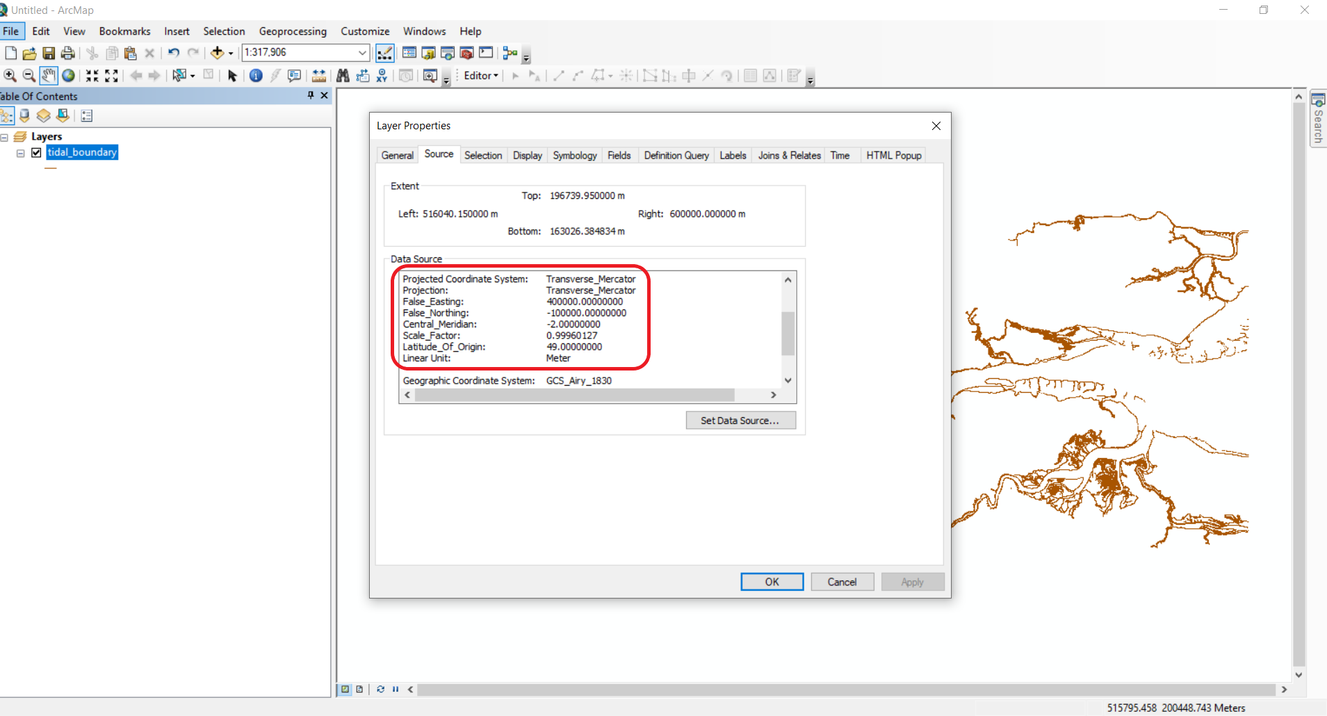
Projected Coordinate System in ArcMap
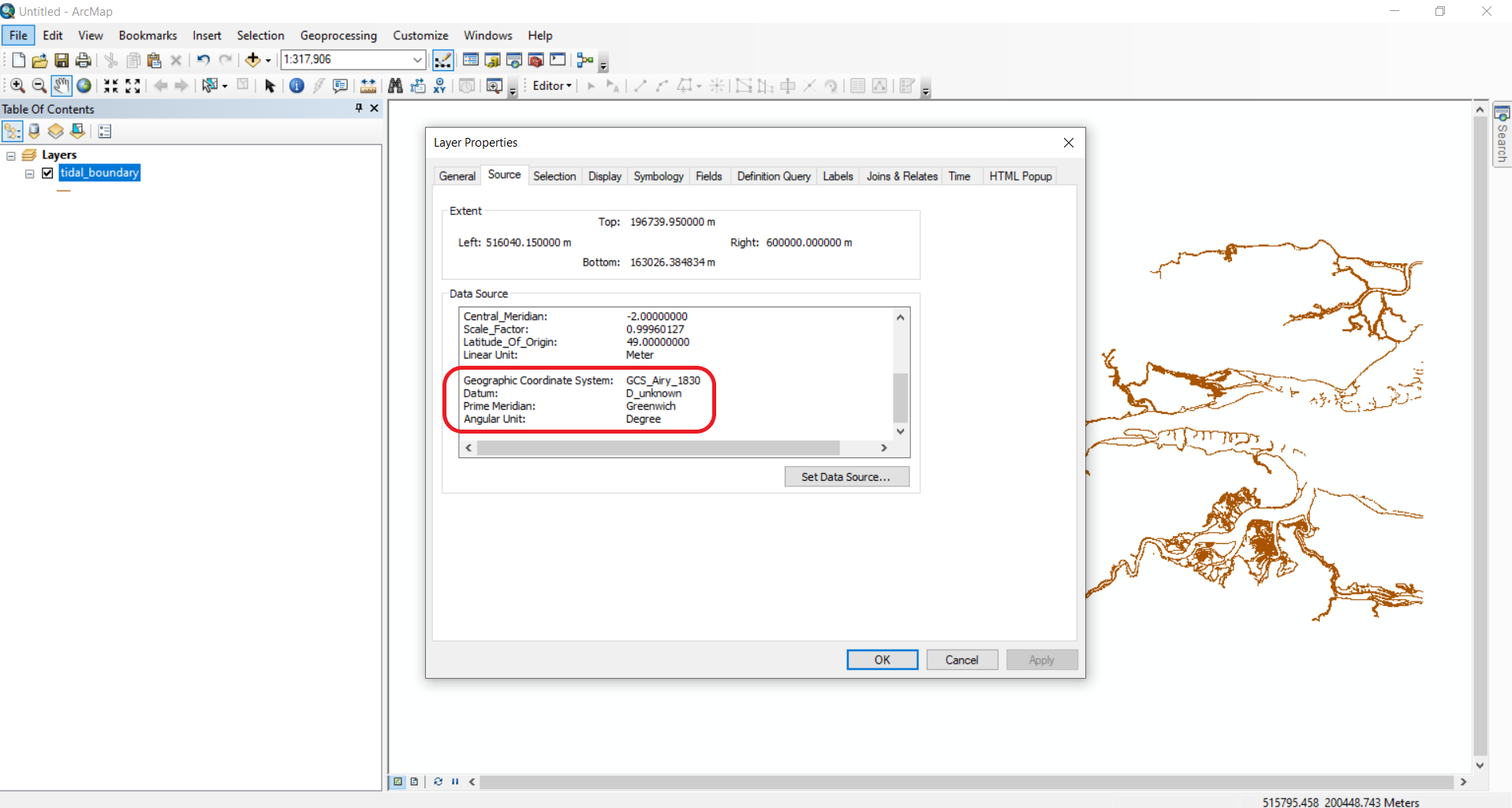
Under Geographic Coordinate System the following parameters are given:
Geographic Coordinate System: It is also set as British National Grid (OSGB 1936).
Datum: The datum that corresponds with the British National Grid (OSGB 1936).
Prime Meridian: Set at Greenwich.
Angular Unit: Set in degrees.
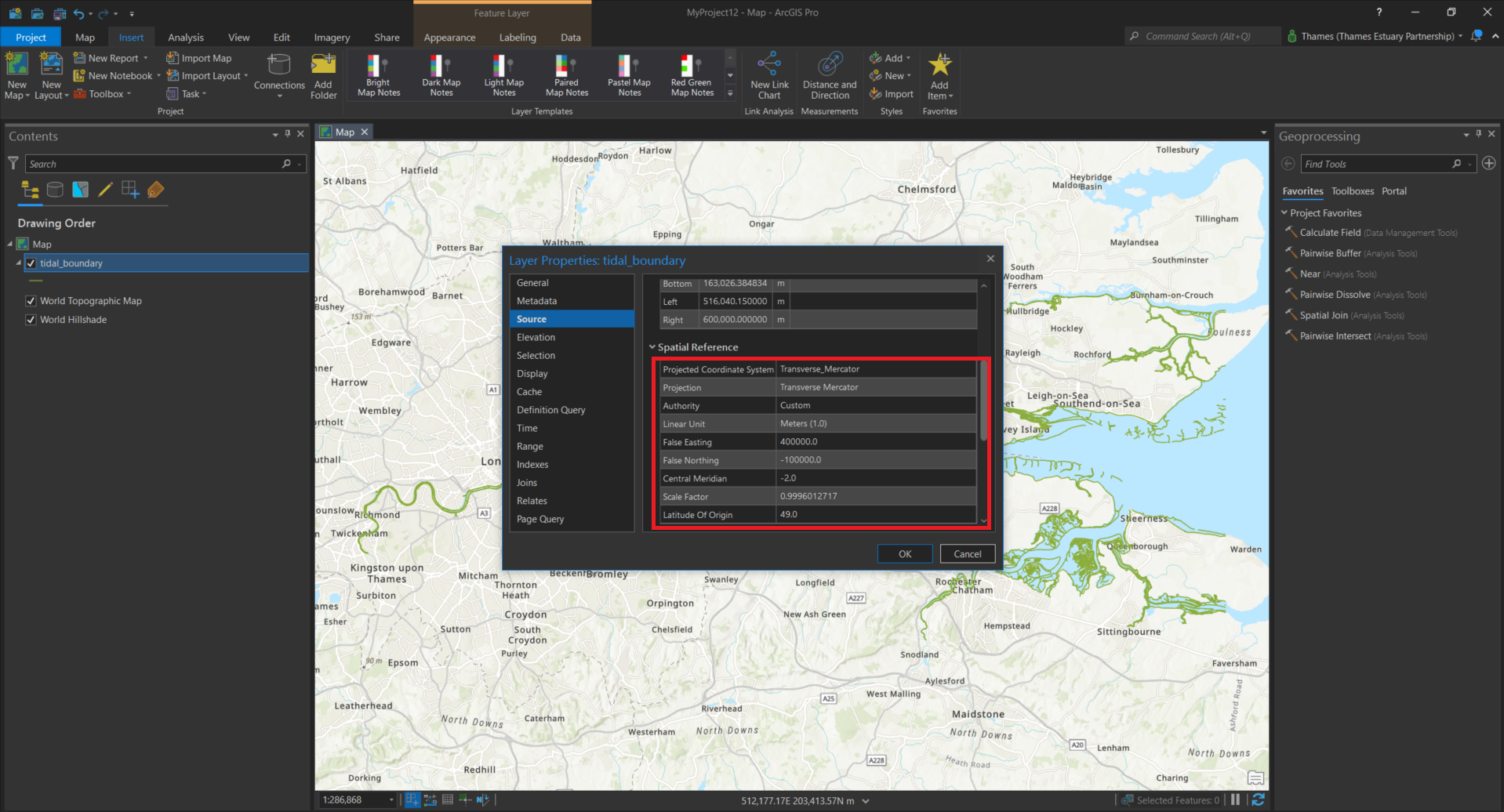
ArcGIS Pro
In addition to the what is under Projected Coordinate System in ArcMap, in ArcGIS Pro there are also:
WKID: Well-known ID (WKID) is a unique identifier number. In PCS, the WKID for the British National Grid is 27700.
Authority: European Petroleum Survey Group (EPSG) was a scientific organisation that carried out oil exploration surveys and compiled datums, spatial reference systems, Earth ellipsoids, coordinate transformations and related units of measurement with their own EPSG code (e.g. for British National Grid EPSG:27700).
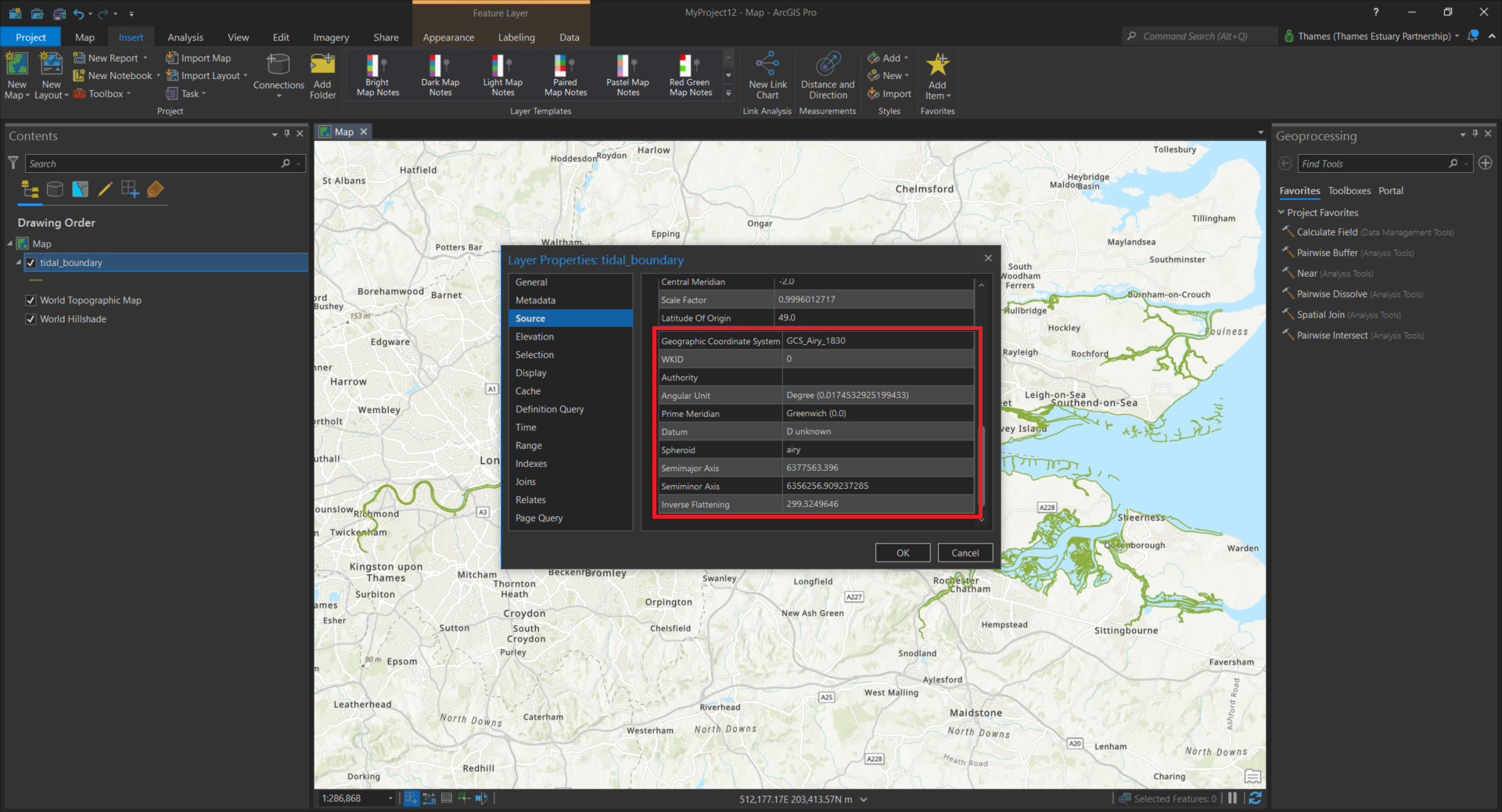
The additional parameters in Geographic Coordinate System are:
WKID: In GCS, the well-known ID (WKID) for the British National Grid is 4277.
Angular Unit: Angles are typically measured in radians rather than degrees. Since a geographic coordinate system uses degrees, a conversion factor must be provided. There are 2*pi radians in 360 degrees and 1 degree equals 0.0174532925199433 radians.
Spheroid: This is the reference spheroid for the coordinate transformation. For the British National Grid this is Airy 1830.
Semi-major axis: This is the radius from the center of the earth to the equator (see ellipsoid).
Semi-minor axis: This is the radius from the center of the earth to the pole (see ellipsoid).
Inverse flattening: 1/f (see ellipsoid), this is the amount of flattening at each pole, relative to the radius at the equator.
Note
The projection method and parameters for the British National Grid is explained here.
Each projection method has its own projection parameter.
List of WKID for geographic coordinate systems and projected coordinate systems in Esri.
what3words
what3words divided the world into 3 metre squares and gave each square a unique combination of three words. Unlike coordinates recorded using GPS devices, these three words will never change providing an accurate location at all times.

Summary
Two types of coordinate reference systems (CRS) in GIS are: Geographic Coordinate Systems (GCS) and Projected Coordinate Systems (PCS).
GCS shows where a certain location is on the surface of the three-dimensional Earth.
GCS is defined by: datum, prime meridian and angular units.
A datum is the mathematical frame of reference that approximates the three-dimensional shape of the Earth for the purpose of measurement. It is based on an ellipsoid (geometric model used to capture the shape of the Earth).
Angular units (latitude (φ) and longitude (λ)) are used to describe locations on the Earth’s surface.
Latitude and longitude can be expressed in three formats: degrees, minutes and seconds (DMS), decimal degrees (DD) and degrees decimal minutes (DDM).
PCS shows how the three-dimensional Earth should be projected on a two-dimensional flat surface.
A map projection uses mathematical formulas to relate spherical coordinates on the globe to planar coordinates using the Cartesian coordinate system.
Map projections can be grouped by types (Cylindrical, Conical, Planar/Azimuthal).
Map projection types can be further grouped by methods (e.g. Lambert Conformal Conic, Albers Equal Area Conic or Equidistant Cylindrical).
Some projection methods use their own coordinate system (e.g. UTM, State Plane or British National Grid).
Web Mercator is a special projection made for web-mapping programs.
Each projection method has its own projection parameters for both GCS and PCS (e.g. false easting, false northing, central meridican, scale factor and so on) in a GIS software.
Coordinate systems can be specifically identified with a WKID. Apart from ESPG, Esri also defines coordinate systems with its own set of numbers.
Reference resources
Other
- A guide to coordinate systems in Great Britain
- A Handy Guide to Measuring the Sky
- A Quick Guide to Using UTM Coordinates
- Coordinate Systems: What’s the Difference?
- Geographic coordinate systems
- Geographic vs Projected Coordinate Systems
- Great Circle Mapper
- How to measure Latitude & Longitude
- Interactive Album of Map Projections 2.0
- Latitude and Longitude Finder
- List of supported map projections in ArcGIS Desktop
- Map Projections
- National Geodetic Survey Data Explorer
- PROJ
- Projections and Coordinate Systems
- Projection parameters
- Spatial reference
- Spatial referencing and coordinate systems
- UTM Grid Zones of the World
- What is the geoid?
- What is the Prime Meridian and why is it in Greenwich?